Mounting plate for solid-state imaging device and method for bonding solid-state imaging device to mounting plate

Inactive Publication Date: 2008-10-14
PENTAX RICOH IMAGING CO LTD
View PDF17 Cites 28 Cited by
  • Summary
  • Abstract
  • Description
  • Claims
  • Application Information

AI Technical Summary

Benefits of technology

[0010]Therefore, an object of the present invention is to provide a mounting plate in which the shape of the opening for bonding the solid-state imaging device is imp

Problems solved by technology

This is because the solid-state imaging device needs to be placed at a proper position relative to a photographing optical system of the digital camera or video camera, and it is difficult to hold the solid-state imaging device at the proper position by itself (i.e., as a single body).
However, the position of the light receiving area relative to a solid-state imaging device package is not uniform, but may be slightly different even in a device manufactured with the identical standards.
Therefore, conventionally, even if the solid-state imaging device package is positioned according to the positioning mark, and bonded on the mo

Method used


Image

  • Mounting plate for solid-state imaging device and method for bonding solid-state imaging device to mounting plate
  • Mounting plate for solid-state imaging device and method for bonding solid-state imaging device to mounting plate
  • Mounting plate for solid-state imaging device and method for bonding solid-state imaging device to mounting plate

Examples


Example

[0028]The present invention will be described below with reference to the embodiments shown in the drawings.

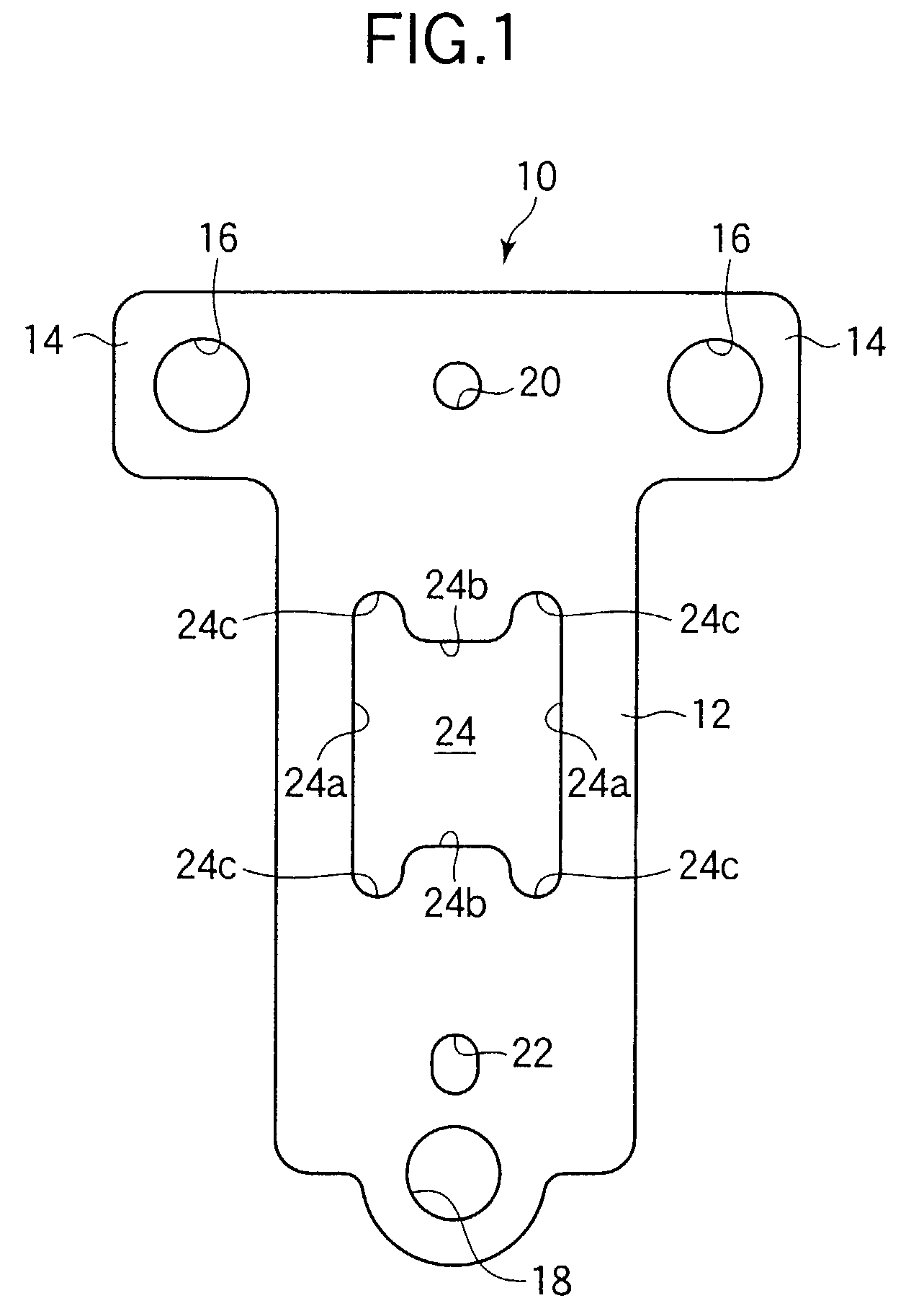
[0029]FIG. 1 shows a plan view of a mounting plate 10 of an embodiment of the present invention. The mounting plate 10 has a rectangular portion 12 and a pair of expanded portions 14 which are provided on an end portion of the rectangular portion 12 and project outward in opposite directions. Namely, the mounting plate 10 has approximately a T-shape as a whole, and can be punched out of a metal plate such as aluminum with a high accuracy.

[0030]A pair of through holes 16 are formed in the expanded portions 14, and a through hole 18 is formed in another end portion of the rectangular portion 12. These through holes 16 and 18 are arranged in such a manner that the centers of the holes 16 and 18 coincide with the vertexes of an isosceles triangle. On the other hand, on an attaching portion of an inner frame housed inside a digital camera or video camera, three screw holes are form...


PUM


Abstract

A mounting plate has an opening provided for bonding a solid-state imaging device thereto. The opening of the mounting plate comprises a first edge portion and a second edge portion. The first edge portion corresponds to a first side of part of the contour of a light receiving area of the solid-state imaging device. The second edge portion corresponds to a second side of part of the contour. The first and second edge portions function as reference lines for positioning the solid-state imaging device over said opening.

Description

BACKGROUND OF THE INVENTION[0001]1. Field of the Invention[0002]The present invention relates to a mounting plate to which a solid-state imaging device is attached, and a method for bonding the solid-state imaging device to the mounting plate.[0003]2. Description of the Related Art[0004]As is well known, a solid-state imaging device such as a CCD is used in a digital camera or a video camera. The solid-state imaging device is available as an electronic package, which is not usually directly mounted in the digital camera or video camera. This is because the solid-state imaging device needs to be placed at a proper position relative to a photographing optical system of the digital camera or video camera, and it is difficult to hold the solid-state imaging device at the proper position by itself (i.e., as a single body).[0005]Therefore, conventionally, the solid-state imaging device is fixed on a mounting plate with an adhesive agent, and the mounting plate is then attached to an inner...

Claims


Application Information

Patent Timeline
IPC IPC(8): H04N3/14H04N5/225H01L27/14G03B17/00H01L27/146H01L31/0203H04N5/335H04N5/372
CPCH04N5/2253H01L31/0203H01L27/14618H01L2924/0002H04N23/54H01L2924/00H05K1/02
Inventor HIRUNUMA, KENHOTTA, KEIICHIFUNATSU, GOUJI
Owner PENTAX RICOH IMAGING CO LTD
Why Eureka
Try Eureka