Method and apparatus for improved temperature control in microfluidic devices

a microfluidic device and temperature control technology, applied in the field of microfluidic devices, can solve the problems of increasing the amount of power delivered to such devices, thermal gradients between reaction channels, and unresolved challenges, and achieve the effect of promoting heat transfer and promoting fluid temperature uniformity

Inactive Publication Date: 2008-10-21
CAPLIPER LIFE SCI INC
View PDF24 Cites 101 Cited by
  • Summary
  • Abstract
  • Description
  • Claims
  • Application Information

AI Technical Summary

Benefits of technology

[0021]The present invention involves a microfluidic system comprising a microfluidic device and a method for using it wherein the temperatures of fluids within the channels of the microfluidic device are controlled to a degree unachievable heretofore. Heat transfer fluids can be applied to the top and / or bottom layers to promote heat transfer. In addition, the geometry of the microchannels and heat generating expedients such as metal traces for carrying heat generating electric current are configured in such a way as to promote uniformity of fluid temperatures within the plurality of microchannels contained within such devices.

Problems solved by technology

However, providing such temperature control and uniformity has proven to be a formidable challenge that those involved in this technology have yet to fully resolve.
However, the tendency has been to increase channel density within such microfluidic devices, which, in turn, increases the amount of power delivered to such devices.
Without adequate removal of heat, “hot spots” on the microfluidic chips can form resulting in thermal gradients between reaction channels.
Variation of channel temperatures can be dramatic, as much as 30° C. across the various parallel microchannels when operating at set points of 95° C. Although this effect can be diminished by using individually controllable power supplies to heat each channel, the resulting complexity in equipment and fabrication costs make such an approach undesirable.

Method used


Image

  • Method and apparatus for improved temperature control in microfluidic devices
  • Method and apparatus for improved temperature control in microfluidic devices
  • Method and apparatus for improved temperature control in microfluidic devices

Examples


Embodiment Construction

[0030]There has been a growing recognition that microfluidic systems comprising microfluidic devices have a unique place in carrying out a number of operations such as PCR for DNA amplification. For example, PCR by temperature cycling is the amplification method that is used for target nucleic acid amplification. It is critical in carrying out such operations that the temperature of fluids within the channels in a microfluidic device be controllable such that temperature profiles be uniform within channels and among different channels, and be capable of being altered at the direction of an operator.

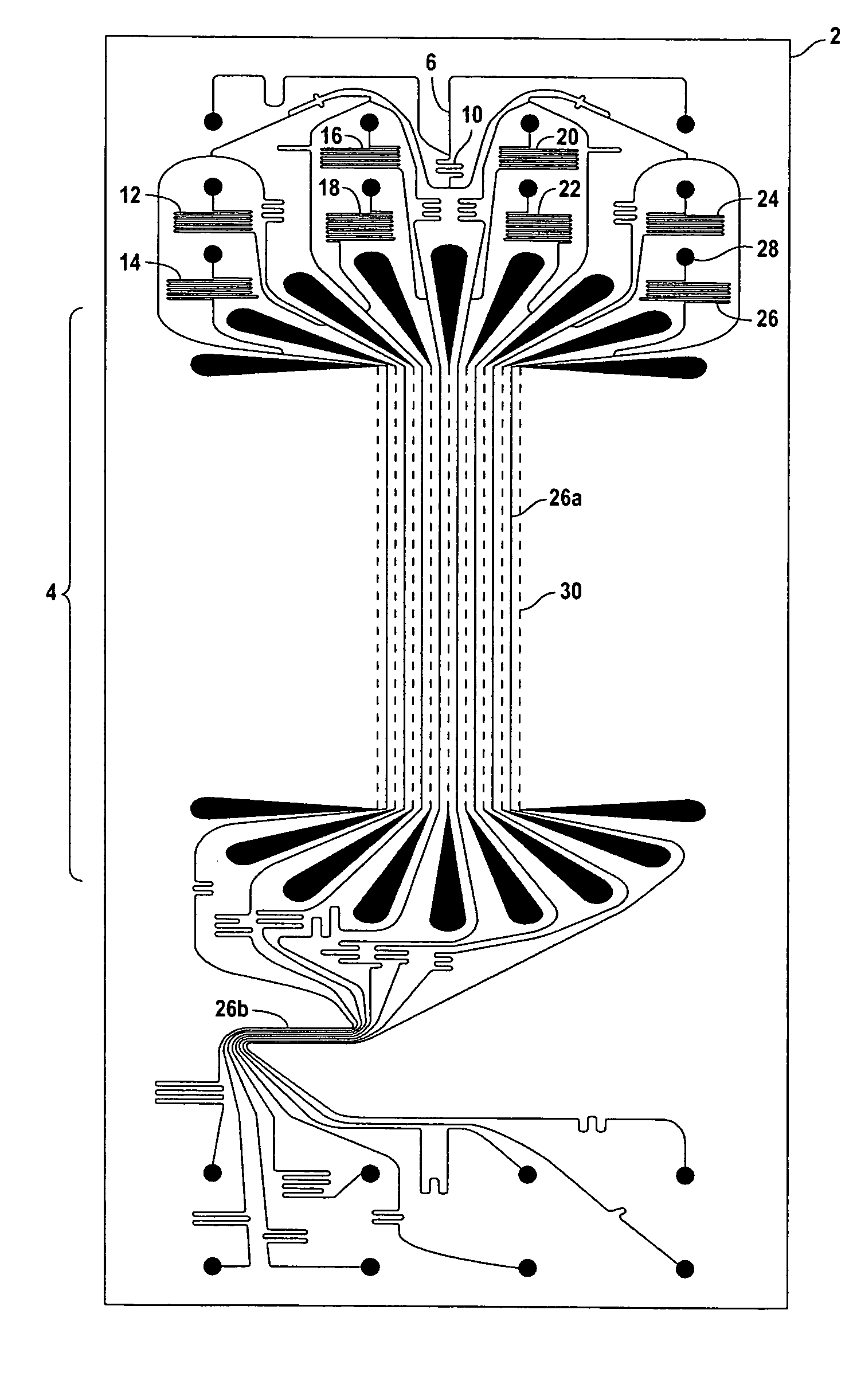
[0031]To heat fluids within the channels of a microfluidic device in a designated heating region (e.g. region 26a of FIG. 1), thermal energy can be generated in heating elements adjacent to the channels in the heating region by passing electrical current through those elements. Heat is generated by increasing current through the elements until the desired temperature is achieved. This pro...


PUM

PropertyMeasurementUnit
temperaturesaaaaaaaaaa

Abstract

A microfluidic system and method for employing it to control fluid temperatures of fluids residing within microchannels of a microfluidic device. The microfluidic device is provided with a top layer and a bottom layer and microchannels configured therebetween. Temperature of the fluid within the microchannels is controlled in various ways including the use of electrical resistive heating elements and by providing zones located in contact with the top and bottom layers of the microfluidic device for circulating heat transfer of fluid therein.

Description

CROSS REFERENCE TO RELATED APPLICATIONS[0001]This application is a continuation-in-part of U.S. patent application Ser. No. 10 / 123,100, which was published on Dec. 26, 2002 as US 2002 / 0197630, and which is incorporated herein by reference. That application claims priority to and benefit of U.S. Provisional Patent Application 60 / 283,527, which was filed on Apr. 12, 2001, and which is incorporated herein by reference.STATEMENT REGARDING FEDERALLY SPONSORED RESEARCH OR DEVELOPMENT[0002]The present invention was made with government funding from the United States National Institute of Standards and Technology (NIST), through the Advanced Technology Program (ATP) under Grant No. 70NANB8H4000, and the United States government has certain rights in the invention.TECHNICAL FIELD[0003]The present invention is directed to microfluidic devices commonly employed in areas such as biotechnology, genetic research, DNA diagnostics and automated high-speed thermocycling. In each instance, careful te...

Claims


Application Information

Patent Timeline
Patent Type & Authority Patents(United States)
IPC IPC(8): F24H1/10C07B61/00C12Q1/68C40B40/06
CPCC12Q1/6818C12Q1/6827B01J2219/00364B01J2219/00495B01J2219/00704B01J2219/00722C07B2200/11C40B40/06C12Q2561/125C12Q2565/543C12Q2565/629C12Q2565/101
Inventor SPAID, MICHAEL A.CHOW, ANDREA W.YURKOVETSKY, YEVGENYSTERN, SETH R.BORONKAY, ALLEN R.JENSEN, MORTEN JUELBROOKS, CARLTON F.SWARTZ, KEN
Owner CAPLIPER LIFE SCI INC
Why Eureka
Try Eureka