Precision insert for molding ferrules and associated methods of manufacture

a technology of inserts and ferrules, applied in the direction of dough shaping, manufacturing tools, instruments, etc., to achieve the effect of promoting ferrule uniformity and low surface roughness

Inactive Publication Date: 2007-08-28
CORNING OPTICAL COMM LLC
View PDF5 Cites 18 Cited by
  • Summary
  • Abstract
  • Description
  • Claims
  • Application Information

AI Technical Summary

Benefits of technology

[0009]In another aspect, the present invention is directed to a method for fabricating a pre-angled precision insert for molding angled, and in some embodiments bumpered, multi-fiber ferrules. The mold insert provides the precise fiber bore and guide pin hole locations and diameters required for high-performance single and multi-mode ferrules. The mold insert is formed from a molding blank consisting of rough dimensions for the ferrule end face features. Starter fiber bore and guide pin holes are then preferably created in the blank using an Electrical Discharge Machining (EDM) process. The fiber bore and guide pin holes are preferably undersized as compared to the desired final dimensioned fiber bore and guide pin hole diameters. In one exemplary mold fabricating process, the fiber bore and guide pin holes may be undersized by about 1 to about 5 microns as compared to the desired final diameters. The final fiber bores and guide pin holes are preferably formed within about 1 to about 2 microns from nominal. The mold insert thickness is oversized to accommodate for grinding in the angle. The angle is then ground into the end face of the insert using a conventional grinder or other suitable tool. Areas on either side of the angled surface are ground to the desired nominal thickness. Once the angle is completed, the features that create the bumper in the ferrule are installed, preferably using an EDM process such as plunge EDM to obtain a desired bumper depth. Final fiber bores and guide pin holes are then installed at the desired locations and hole sizes using a Poly Crystalline Diamond (PCD) grinding tool. The PCD grinding tool provides low surface roughness in the holes and is used to create the final dimensioned bore and hole locations and diameters. Final dimensioned bores and holes are preferably ground to about a 0.3 micron maximum offset, more preferably about a 0.1 micron maximum offset. Once the final holes are formed, fiber bore forming pins and guide pin hole forming pins may be loaded into the blank and the blank loaded into a molding tool.
[0010]In another aspect, the present invention is directed to a method for molding angled multi-fiber fibers using a precision mold insert that eliminates the need for machining a ferrule end face subsequent to the molding process. The precision mold insert may also be used to mold angled ferrules including bumpers that provide a polishing guide surface for polishing the plurality of optical fibers of the ferrule to a predetermined height and angle. Further, the introduction of bumpers to the ferrule allows the plurality of optical fibers to be polished without removing an appreciable amount of material from the end face, and in particular, without altering the region of interest of the ferrule. Thus, the precision mold insert and method for molding using the insert allows for multi-fiber ferrules to be polished without removing material from the surface of the end face surrounding the optical fiber bores, thus maintaining the positions of the optical fiber bores as molded. In contrast, conventional molding and subsequent machining methods result in movement of the fiber bores and guide pin holes as end face material is ground away to introduce an angle to the ferrule end face. Forming the final fiber bores and guide pin holes into the mold insert after the angle is installed permits the location and diameter of each hole to be precisely controlled, thus promoting ferrule uniformity.

Problems solved by technology

In contrast, conventional molding and subsequent machining methods result in movement of the fiber bores and guide pin holes as end face material is ground away to introduce an angle to the ferrule end face.

Method used


Image

  • Precision insert for molding ferrules and associated methods of manufacture
  • Precision insert for molding ferrules and associated methods of manufacture
  • Precision insert for molding ferrules and associated methods of manufacture

Examples


Embodiment Construction

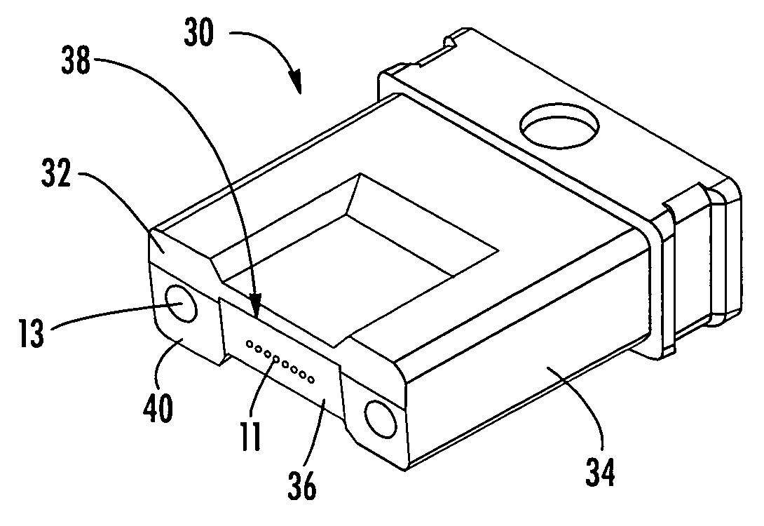
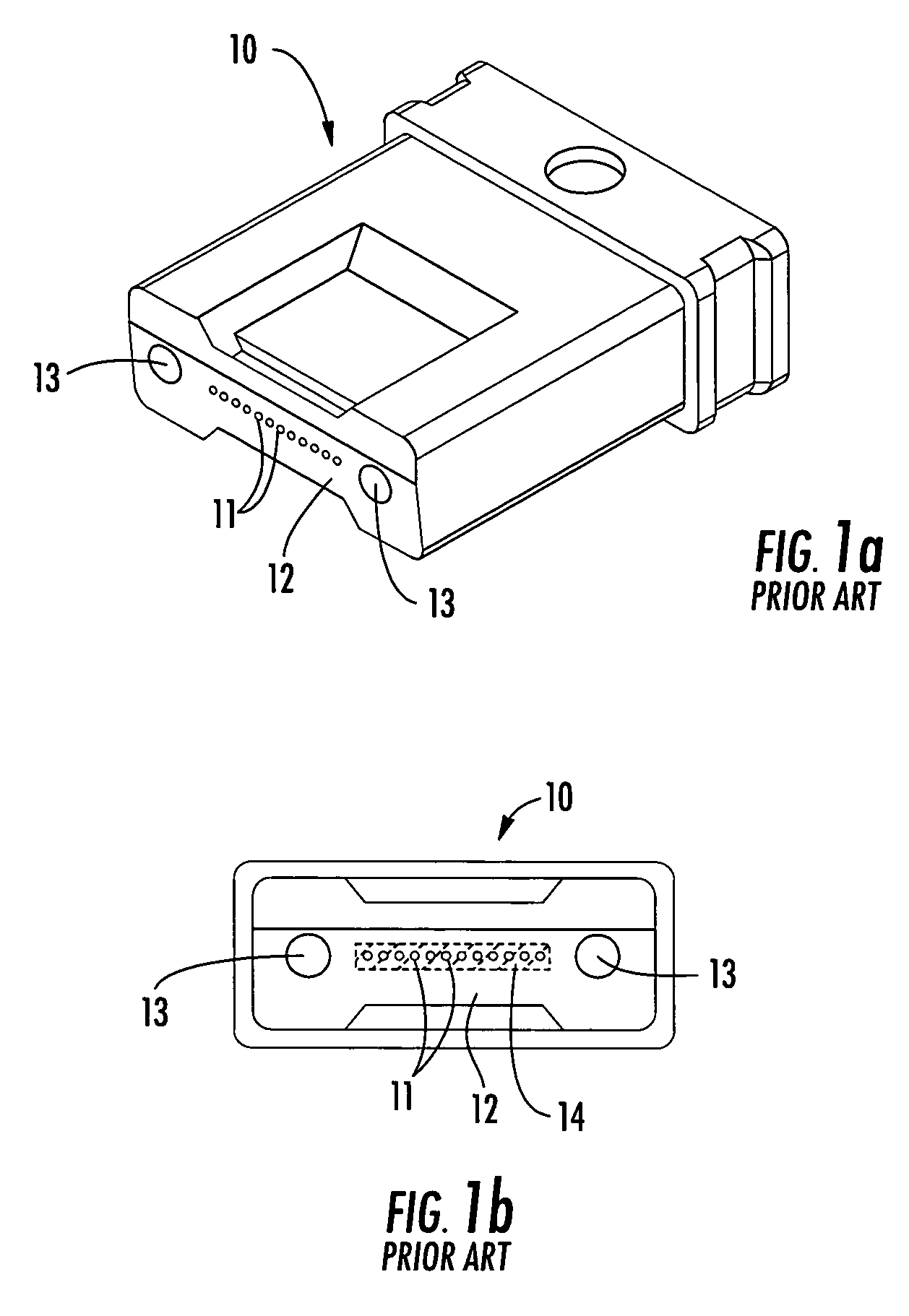
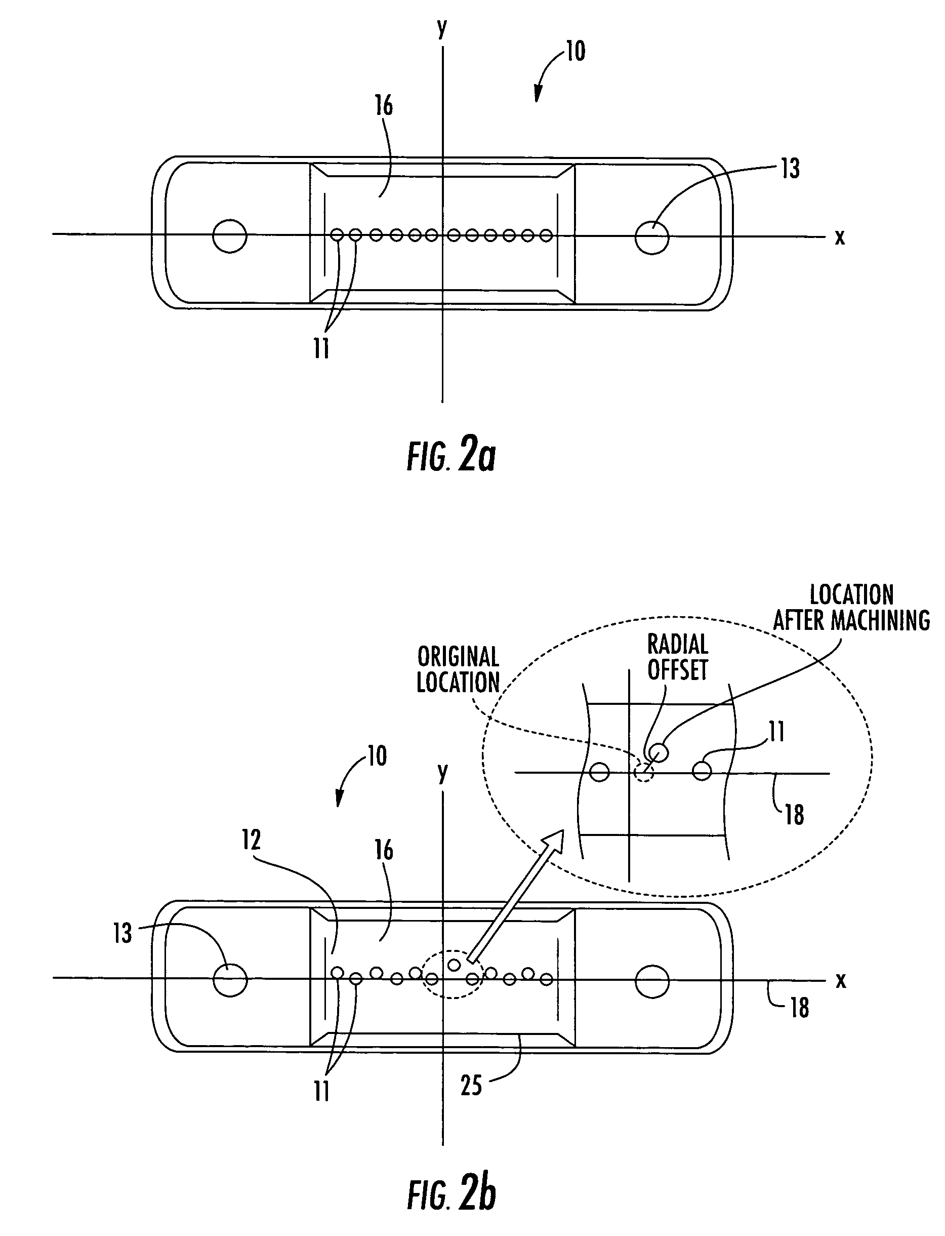
[0027]Reference will now be made in detail to the present preferred embodiments of the invention, examples of which are illustrated in the accompanying drawings. Whenever possible, the same reference numerals will be used throughout the drawings to refer to the same or like parts. Although a precision mold insert for molding angled and bumpered multi-fiber ferrules is described and shown throughout the figures, the precision mold insert may be modified to remove the bumper forming features. However, as described below, bumpers disposed about opposing sides of a region of interest of a ferrule end face are advantageous in that they provide a polishing guide surface for polishing the one or more optical fibers of the ferrule to a uniform height and predetermined angle, such as about an 8 degree angle common in Angled Physical Contact (APC) type connectors used in the art. Further, although a specific number of optical fibers are shown throughout the various figures, it is envisioned t...


PUM


Abstract

A precision mold insert and method for manufacturing angled or angled and bumpered multi-fiber ferrules. The precision mold insert includes an angled end face forming portion, one or more optional bumper forming portions, one or more fiber bores for receiving one or more fiber bore forming pins, and one or more guide pin holes for receiving one or more guide pin hole forming pins. A method for manufacturing a precision mold insert for molding angled or angled and bumpered multi-fiber ferrules utilizing electrical discharge machining (EDM) process and/or a poly crystalline diamond (PCD) grinding tool is provided. The mold insert is used to produce a multi-fiber ferrule having a pre-molded angled end face that is not machined, polished or otherwise altered subsequent to the molding process. The ferrule may also include bumpers for polishing end portions of optical fibers positioned within the fiber bores without altering the angled end face.

Description

BACKGROUND OF THE INVENTION[0001]1. Field of the Invention[0002]The present invention relates generally to a mold insert for molding multi-fiber ferrules, and more specifically, to a precision insert for molding angled and bumpered multi-fiber ferrules and associated methods of manufacture.[0003]2. Technical Background[0004]Fiber optic cables require optical connectors or ferrules to link discrete segments of optical fibers. As used herein, the term “ferrule” refers to a component of a connector assembly that receives a terminal end of one or more optical fibers or an optical fiber ribbon and aligns with an opposing ferrule to optically couple corresponding optical fibers to transmit an optical signal or signals. In order to minimize signal losses across a ferrule-to-ferrule optical connection, it is important that the opposing optical fibers be precisely aligned. The precision of opposing optical fibers is more sensitive with multi-fiber ferrules due to the presence of multiple opt...

Claims


Application Information

Patent Timeline
Patent Type & Authority Patents(United States)
IPC IPC(8): G02B6/38A01J21/00G02B6/26
CPCG02B6/3865G02B6/3882G02B6/3885
Inventor DEAN, JR., DAVID L.MALANOWSKI, ALAN J.CODY, JOSEPH T
Owner CORNING OPTICAL COMM LLC
Why Eureka
Try Eureka