
Optical transmitter system

a technology of optical transmitter and optical receiver, which is applied in the direction of multiplex communication, transmission monitoring, instruments, etc., to achieve the effect of limiting the power level of any escape radiation and preventing accidental escape radiation

Inactive Publication Date: 2008-10-21
TELEFON AB LM ERICSSON (PUBL)
View PDF6 Cites 1 Cited by
  • Summary
  • Abstract
  • Description
  • Claims
  • Application Information

AI Technical Summary

Benefits of technology

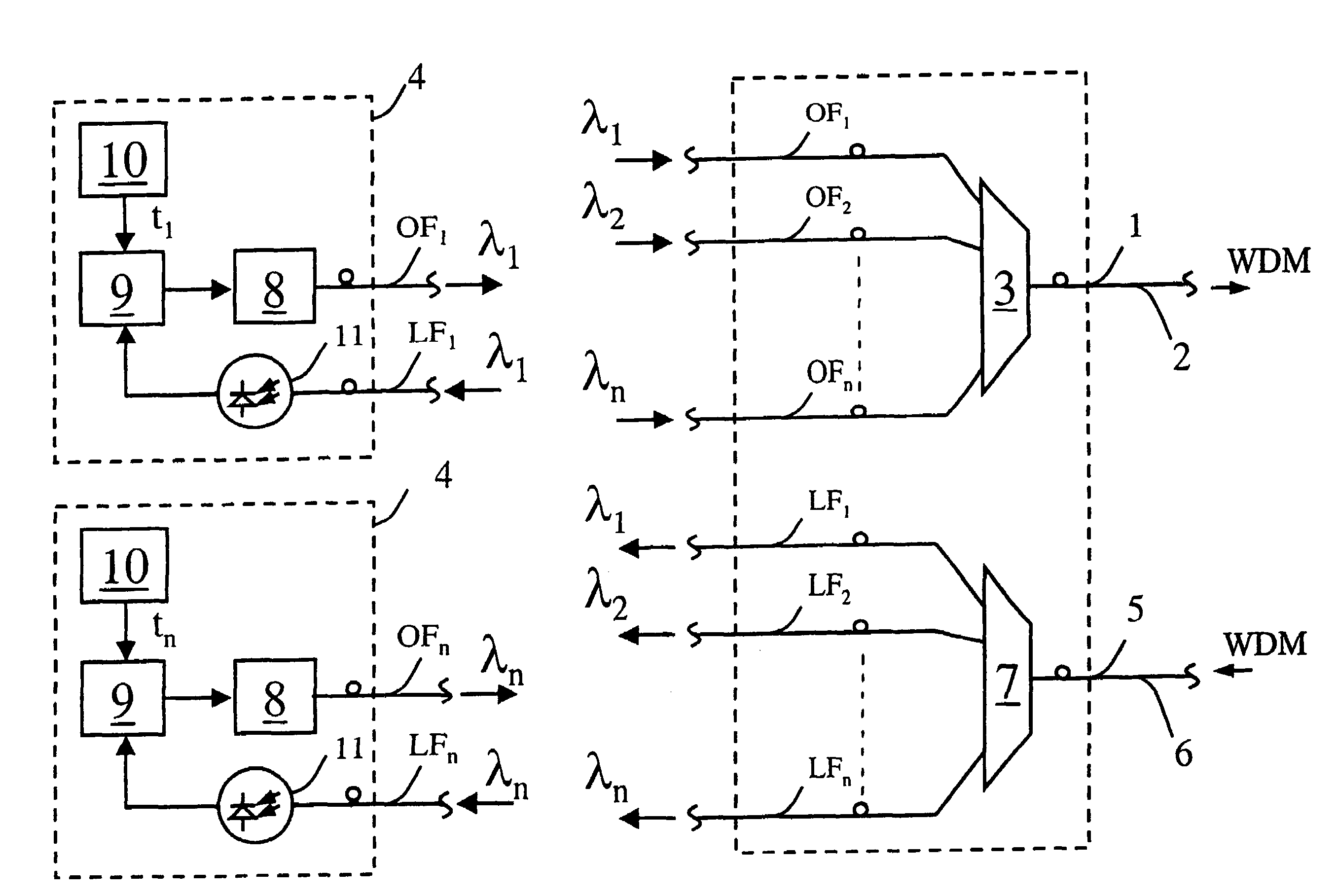
[0012]Detection of the loss of an optical radiation component by the respective receiver is taken as an indication that there may be a break in the transmission element, or at least a problem in the transmitter of the radiation component and the supply of this radiation component is accordingly interrupted by the transmitter. Clearly the loss of all of the radiation components at the respective receivers, which will result when there is a break in the transmission element, will result in the transmitter system interrupting the supply of all radiation components thereby preventing accidental escape of radiation from the break. Since the transmitter system reactivates supply of the radiation components at different respective restart times this ensures that even if there is a break when the system restarts only one, or only a few, of the radiation components will be present thereby limiting the power level of any escaping radiation. Moreover since each transmitter is restarted at its own restart time, independent of any other transmitter, the present invention is particularly suited to a passive WDM system in which there is little or no central control function between the transmitters.

Problems solved by technology

For WDM systems the optical power conveyed by a fibre is the sum of the separate component (wavelength channel) power levels and it is undesirable to limit this total power level to a safe level since this would unduly limit the span of the optical link between the transmitter and receiver.
A problem arises however in passive WDM systems in which the wavelength channels are passively combined and each originates from optical sources that operate in complete independence of one another.

Method used


Image

  • Optical transmitter system
  • Optical transmitter system

Examples


Embodiment Construction

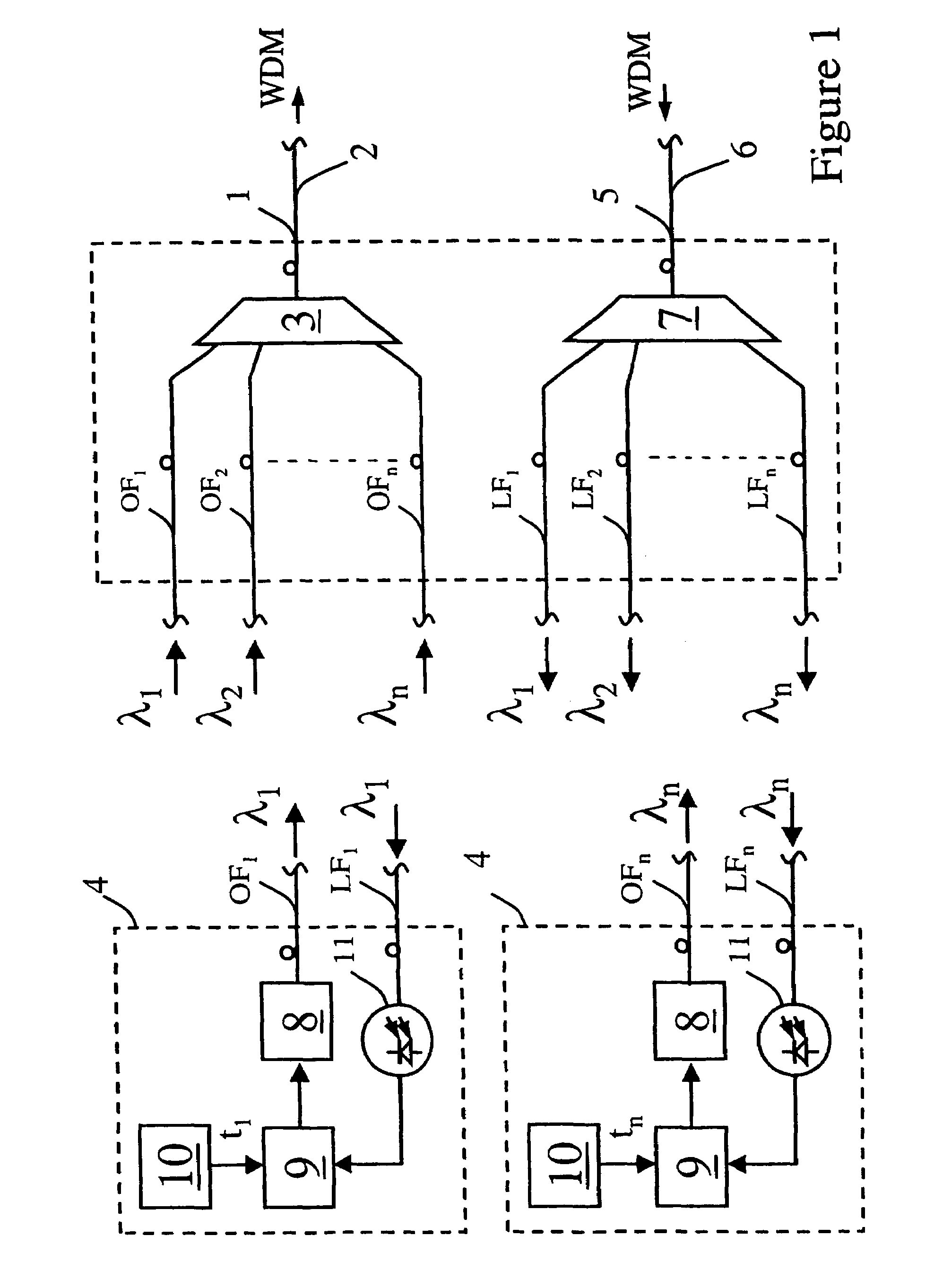
[0020]Referring to the FIG. 1, the optical WDM transmitter / receiver system includes an output port 1 for connection to an output optical fibre 2 capable of transmitting a WDM optical signal comprising a plurality n of different wavelength channels (λ1 to λn), optical radiation components. Typically the system would be configured for operation in C-band (i.e. a free-space wavelength of 1530 to 1565 nm) and have 32 wavelength channels with wavelength spacing between channels of 0.8 nm. It will be appreciated that the present invention applies equally to other wavelength ranges of operation having differing numbers of channels / channel spacings.

[0021]The WDM signal is generated by a wavelength selective multiplexer 3 which passively combines the individual wavelength channels (λ1 to λn) from a respective optical fibres OF1 to OFn. As is known the wavelength selective multiplexer 3 could typically comprise an arrayed waveguide grating or cascaded dichroic filters. Each fibre OF1 to OFn i...


PUM


Abstract

An optical transmitter system supplies a plurality of different wavelength optical radiation components to a transmission element which, in operation, is connected to the transmitter system for conveying the different wavelength radiation components to a respective receiver. The transmitter system detects a loss of a wavelength radiation component at the respective receiver. The supply of the wavelength component is interrupted in response to a detection of loss of the wavelength component at the receiver. A timing circuit provides respective restart times which differ one to another for the wavelength radiation components. The supply of the wavelength component is restarted, following an interruption, at the restart time provided by the timing circuit.

Description

BACKGROUND OF THE INVENTION[0001]The invention relates to an optical transmitter system and more especially to an optical transmitter system for use in a wavelength division multiplex (WDM) optical communications system.[0002]In conventional optical communication systems, communications traffic is communicated between a transmitter and receiver by means of optical radiation which is modulated with the communications traffic and which is conveyed by optical waveguiding means, typically an optical fibre. Optical radiation in the context of this patent application is defined as electromagnetic radiation within a free-space wavelength range from 560 nm to 2000 nm, although a free-space wavelength of substantially 1550 nm is a preferred part of this range.[0003]In operation of optical communications system an optical fibre can suffer mechanical damage including breakage and it is desirable to prevent personnel in the vicinity of such a break being exposed to the escape of optical radiati...

Claims


Application Information

Patent Timeline
Patent Type & Authority Patents(United States)
IPC IPC(8): H04J14/02H04B10/00H04B10/077H04B10/079
CPCH04B10/077H04B10/07955H04J14/02H04J14/0282H04J14/0297H04J14/0246H04J14/025H04J14/0227H04J14/0279
Inventor BARKER, ANDREW JAMESARNOLD, PHILIP ANDREW
Owner TELEFON AB LM ERICSSON (PUBL)
Learn More