Steering wheel for a motor vehicle

a technology for steering wheels and motor vehicles, applied in steering controls, mechanical control devices, controlling members, etc., can solve problems such as mechanical wear, functional impairments and faults of activation devices, and achieve simple and cost-effective manufacture, maintenance-free, and increase impairment

Inactive Publication Date: 2008-10-28
TAKATA PETRI AG
View PDF19 Cites 32 Cited by
  • Summary
  • Abstract
  • Description
  • Claims
  • Application Information

AI Technical Summary

Benefits of technology

[0006]An object of the present invention is to make available a steering wheel with at least one activation device, with the activation device having a maintenance-free and reliable function over the entire service life of the motor vehicle without increasing impairment occurring over the course of the service life. A further object of the invention is to provide a steering wheel with at least one activation device, which steering wheel has, in addition to the function of enabling the driver of a vehicle to control and / or regulate a parameter of a motor vehicle assembly, integrated at least one further functionality, thus permitting simpler and more cost-effective manufacture.
[0010]Such a sensor device operates without mechanically moving parts and during the service life of the steering wheel it is, as described above, independent of general scratching and soiling of the functional faces. For this reason, it is an activation device which ensures a permanent and continuously reliable function. In addition, the functionality of the distance measurement and / or speed measurement of the objects located above the functional faces of the sensor device permits further functions to be integrated without requiring further separate devices in order to do so.
[0014]It is advantageous to arrange the functional face of the sensor device in the steering wheel rim or on a steering wheel spoke in such a way that the driver of the vehicle reaches the functional face with one of his fingertips without having to take his hand off the steering wheel rim in order to do so. In this way, the driver of the vehicle can steer the vehicle and at the same time control and / or regulate parameters of a motor vehicle assembly by means of the sensor device. Of course the thumb counts as a finger in the sense of the present invention. The feature of the fingertip which is used within the scope of the present invention essentially comprises the region of the first part of the finger.
[0015]The sensor device is preferably embodied in such a way that the driver of the vehicle generates a switch-off or switch-on signal for a function of an assembly of the motor vehicle by tapping the functional face with a fingertip. Since the electronic evaluation system of the sensor device can differentiate between an object approaching without touching the functional face, in this case a fingertip, and the fingertip tapping on the surface or stroking the functional face, undesired malfunctions of the activation device can be effectively avoided. In addition to the avoidance of malfunctions mentioned above by virtue of a corresponding evaluation of measurement signals, it is advantageous to arrange the functional face of at least one sensor device in a depression in the steering wheel. The depression is embodied here in such a way that the possibility of the driver of the vehicle unintentionally touching the functional face with his hands during the process of steering is ruled out. This is appropriate as an additional measure in particular if the functional faces are arranged in areas of the steering wheel which the driver of the vehicle usually touches with his hands during the process of steering.
[0019]One preferred variant of the invention provides for the functional face of the sensor device to be arranged on a bulge of the steering wheel rim projecting in the direction of the hub element. Such bulges which are formed organically in the direction of the axis of rotation of the steering wheel starting from the contour of the internal diameter of the steering wheel rim are known from the prior art for motor vehicle steering wheels and have the purpose of providing the driver of the vehicle with the possibility of an alternative position for placing his hands on the steering wheel rim. This prevents the musculature of the hands of the driver of the vehicle from becoming fatigued.
[0020]A particularly preferred embodiment of the steering wheel provides for a second sensor device in the region above the axis of rotation of the steering wheel to be arranged symmetrically with respect to the sensor device in the straight-ahead position of the steering wheel. This results in one sensor device which is assigned to the left hand of the driver of the vehicle and one which is assigned to the right hand of the driver of the vehicle. A further embodiment of the steering wheel according to the invention has at least one functional face, extended along an axis of extent, of a sensor device, with this extended functional face being arranged on the steering wheel spokes and / or on the steering wheel hub, and the extension of the extended functional face being formed transversely with respect to the axis of extent in such a way that no significant movement of a fingertip of a driver of a vehicle transversely with respect to the direction of extent is possible. In this way, a functional face is made available whose operating direction, which corresponds to the axis of extent, can again be found in a purely haptic way by a driver of a vehicle without him having to divert his eyes from the traffic situation of the motor vehicle in order to do so.

Problems solved by technology

With respect to the previous activation devices, a first disadvantage is that owing to their mechanical component they have a force / travel characteristic curve and are thus subject to mechanical wear.
As a result, during the course of the service life of a motor vehicle the activation devices may be subject to functional impairments and faults.

Method used


Image

  • Steering wheel for a motor vehicle
  • Steering wheel for a motor vehicle
  • Steering wheel for a motor vehicle

Examples


first embodiment

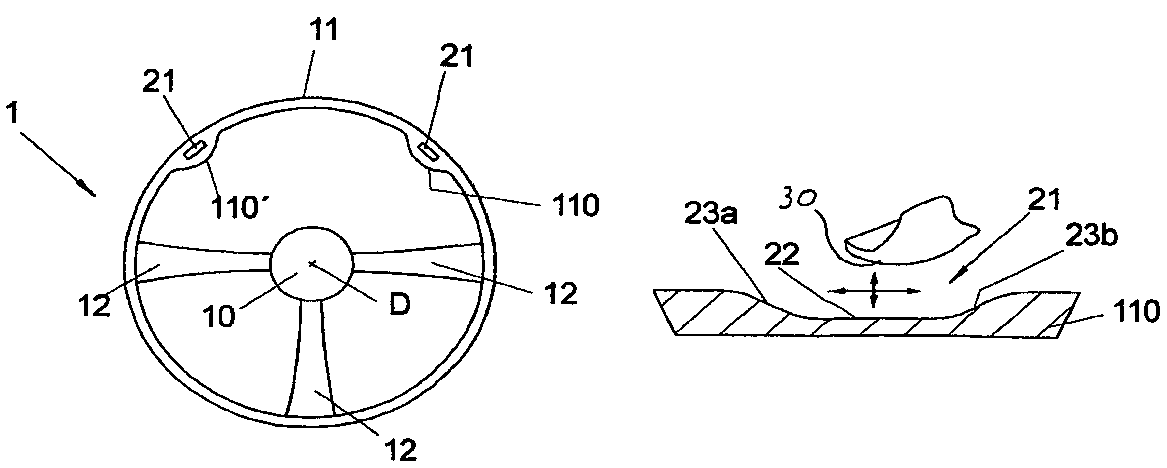
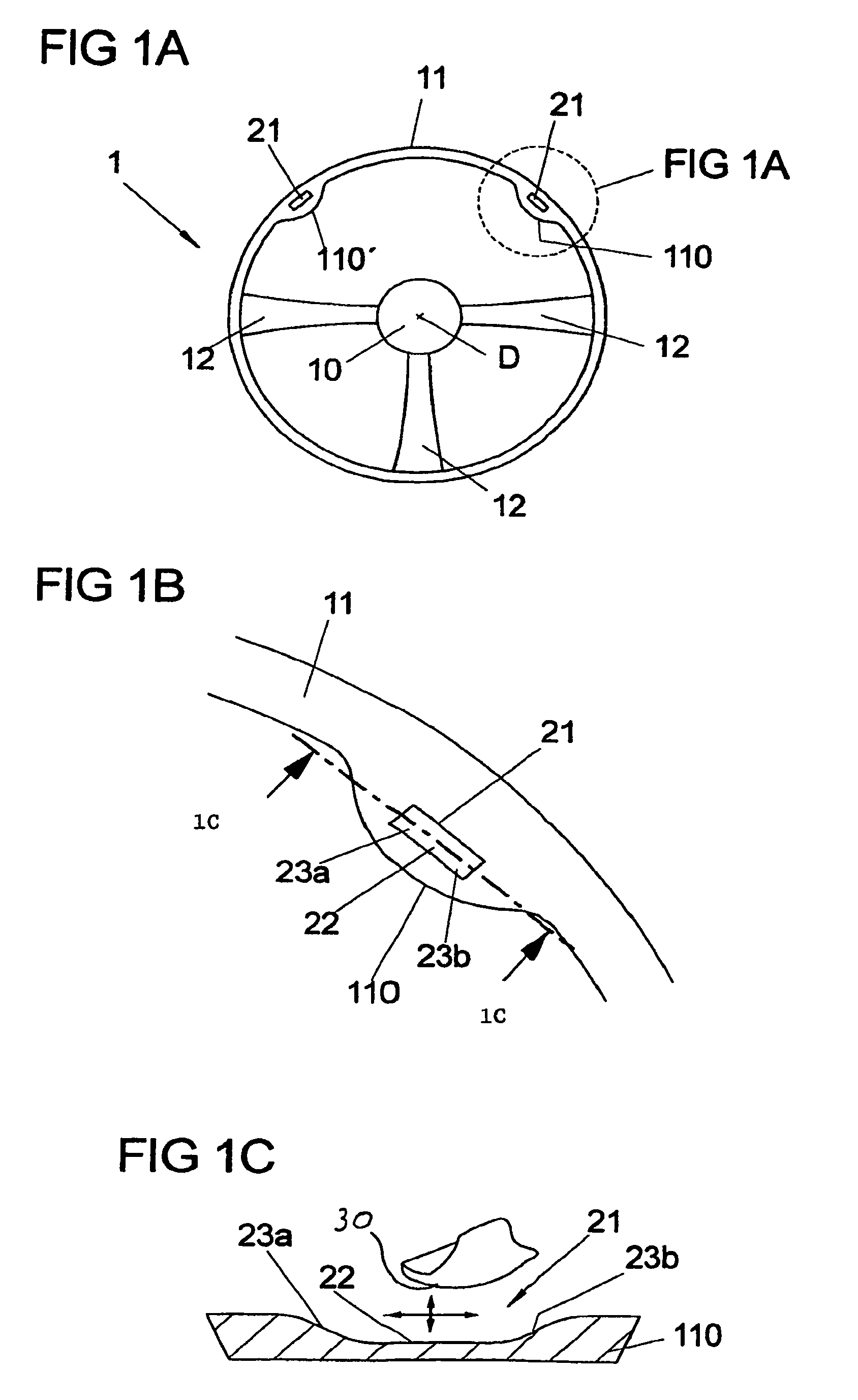
[0035]the steering wheel 1 which is illustrated in FIG. 1A comprises an annular steering wheel rim 11 with an outer contour which is essentially circular. This steering wheel rim 11 is attached, fixed in terms of rotation, to the hub element 10 arranged in the center of the circular outer contour of the steering wheel rim 11 by means of three steering wheel spokes 12 which start from the steering wheel rim 11 and are directed inward.

[0036]FIG. 1A shows the hub element 10 in a circular shape in a plan view. The outer shape of the hub element 10 is influenced, on the one hand, by the fact that it usually accommodates an airbag module. Furthermore, the visual appearance which is expressed in particular in its geometric shape plays an important role for the design in the passenger compartment of the vehicle. Any other geometric embodiment of the hub element 10 which departs from the illustration selected in FIG. 1A is also covered by the invention.

[0037]The same applies to the geometric...

second embodiment

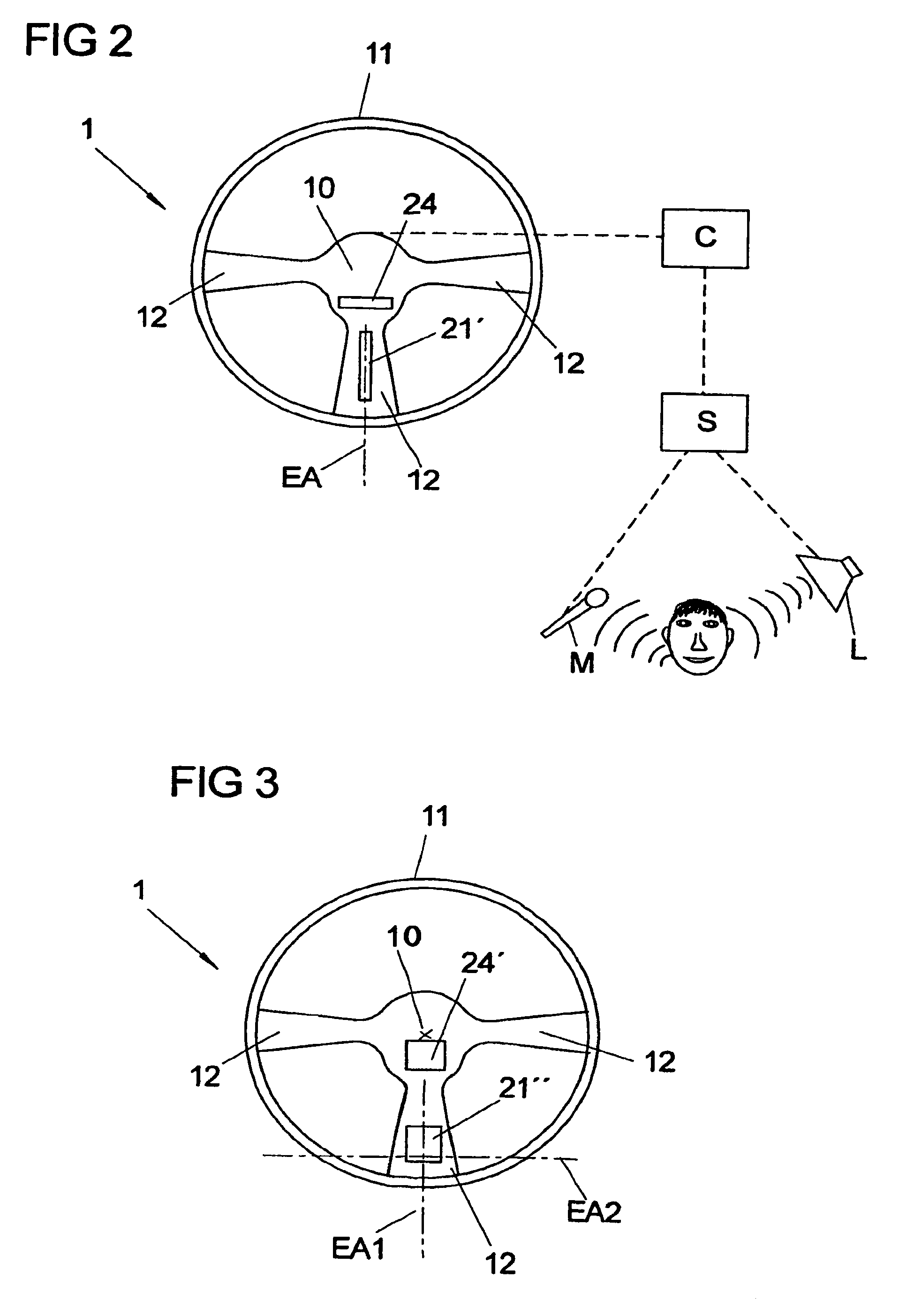
[0047]FIG. 2 shows the steering wheel 1 according to the invention. The basic design of the steering wheel 1 corresponds to that shown in FIG. 1A. The statements made with respect to FIG. 1A therefore apply correspondingly to the matching features. Identical components are provided with identical reference symbols.

[0048]In contrast to the first embodiment of the steering wheel 1, a sensor device with an extended functional face 21′ is not arranged in the region of a bulge on the steering wheel rim 11 but rather on a steering wheel spoke 12. If the steering wheel spoke 12 is one which is grasped by the hands of a driver of a vehicle during customary steering movements owing to the arrangement of said steering wheel spoke 12, the arrangement of the extended functional face 21′ in a depression is not necessary.

[0049]With the steering wheel which is shown in FIG. 2, all that is probable is that a driver of a vehicle grasps the two horizontally arranged steering wheel spokes 12. For this...

third embodiment

[0055]FIG. 3 illustrates the steering wheel 1 according to the invention. The basic design of the steering wheel 1 corresponds to that shown in FIGS. 1A and 2. The preceding statements therefore apply correspondingly to the matching features. Identical components are provided with identical reference symbols.

[0056]In contrast to the first two embodiments of the steering wheel 1, in the third embodiment of the steering wheel 1 a sensor device is provided with a functional face 21″ which extends on the lower steering wheel spoke 12 as an extended functional face 21″ along a first axis EA1 of extent and a second axis EA2 of extent which is arranged perpendicularly with respect to the first axis. The first axis EA1 of extent starts from the axis D of rotation of the steering wheel 1 and runs in the radial direction via the lower steering wheel spoke 12 to the steering wheel rim 11. The second axis EA2 of extent runs perpendicularly with respect to the first axis EA1 of extent, essential...


PUM


Abstract

A steering wheel for a motor vehicle is provided having a hub element, a steering wheel rim, at least one steering wheel spoke for attaching the steering wheel rim to the hub element and at least one activation device which is arranged on the hub element, the steering wheel rim or the steering wheel spoke for controlling and / or regulating an assembly of a motor vehicle. The activation device is preferably embodied as an optical reflection sensor device with a functional face. Such a sensor device operates without mechanically moving parts and during the service life of the steering wheel it is independent of general scratching and soiling of its functional faces. In addition, the functionality of the measurement of distances and / or speeds of the objects located above the functional faces of the sensor device permits further functions to be integrated without requiring further separate devices in order to do so.

Description

FIELD OF THE INVENTION[0001]The present invention relates to a steering wheel for a motor vehicle. In addition, the invention relates to a method using such a steering wheel.BACKGROUND OF THE INVENTION[0002]The prior art has disclosed motor vehicle steering wheels having a hub element, a steering wheel rim, at least one steering wheel spoke for attaching the steering wheel rim to the hub element and at least one activation device which is arranged on the hub element, on the steering wheel rim or on the steering wheel spoke and has the purpose of controlling and / or regulating a parameter of an assembly of a motor vehicle.[0003]Arranging activation devices on the steering wheel itself enables the driver of a motor vehicle to control and / or regulate various parameters of assemblies of the motor vehicle while driving without having to take his hands off the steering wheel. This constitutes an important contribution to vehicle safety.[0004]Customary parameters of motor vehicle assemblies...

Claims


Application Information

Patent Timeline
Patent Type & Authority Patents(United States)
IPC IPC(8): B60R21/16B60R11/00B60R11/02B60R21/01B60R21/015B62D1/04B62D1/06
CPCB62D1/046B62D1/06B60R21/01542B60K2350/928B60R11/0264B60R2011/001Y10T74/20834B60R2021/01095B60K2370/782
Inventor WEBER, HELMUTHMULLER, HORST
Owner TAKATA PETRI AG
Why Eureka
Try Eureka