Radiographic medical imaging system using robot mounted source and sensor for dynamic image capture and tomography

a technology of which is applied in the field of radiographic medical imaging systems using a robotic mounted source and sensor for dynamic image capture and tomography, can solve the problems of difficult direct observation or quantification of joint motion, inability to assess with normal dynamic joint load or muscle load, and difficulty in accurate assessment of joint motion

Active Publication Date: 2008-10-28
UNIV OF FLORIDA RES FOUNDATION INC
View PDF4 Cites 144 Cited by
  • Summary
  • Abstract
  • Description
  • Claims
  • Application Information

AI Technical Summary

Benefits of technology

[0017]The robotic arms include preferably including at least one position sensor. The system can provide unrestricted motion of the source relative to said detector and thus provide cone-beam computed tomography using imaging paths including paths others than a center of rotation located midway between said the source and said detector.

Problems solved by technology

Unfortunately, accurate assessment of joint motion is challenging.
The joints lay beneath layers of skin, muscle and fat that make direct observation or quantification of joint motion difficult.
Further complication arises because motion of many joints is significantly influenced by muscle contraction and joint load.
These techniques permit detailed measurements of joint motion, but do not permit assessment with normal dynamic joint loads or muscle loading.
However, MoCap relies on markers placed at the skin surface, which cannot provide accurate bone motion measures when there is significant muscle / skin / fat overlying the joint, such as the knee, hip, shoulder, or spine.
However, the utility of this measurement approach is limited by factors including activity restrictions, anatomy limitations, exposure to ionizing radiation and bone model generation.
The challenge is finding clinically important activities where the joint remains in a small volume of space suitable for fluoroscopic observation generally within a 23-30 cm field of view.
However, it has not been possible to observe knee motions during normal ground-level steady walking, stair descent, or chair sit / stand.
Furthermore, available imaging systems do not permit observations centered less than ˜100 cm from the ground, requiring platforms to elevate the subject into the field of view.
This means more equipment is required, the subject is elevated into a visually uncomfortable position, and accessory sensors like floor-mounted force plates for measuring ground reaction forces are not easily used.
However, it precludes fluoroscopic observation of the low back during relevant lifting activities due to a small field of view.
Similarly, it is impossible to obtain a transverse view of the patella, a so-called skyline view, during a chair-rise or bicycle activity without an imaging system that can dynamically align the view to the anatomy of interest.
Similar arguments apply to the shoulder, foot & ankle and hip where biomechanically interesting or clinically important observations are not possible because of the limited field of view or immobility of existing radiographic imaging systems.
However, it is inconvenient, expensive and time-consuming to obtain separate tomographic scans of the patient or study subject to create the bone-models required for dynamic radiographic motion analysis.

Method used


Image

  • Radiographic medical imaging system using robot mounted source and sensor for dynamic image capture and tomography
  • Radiographic medical imaging system using robot mounted source and sensor for dynamic image capture and tomography
  • Radiographic medical imaging system using robot mounted source and sensor for dynamic image capture and tomography

Examples


Embodiment Construction

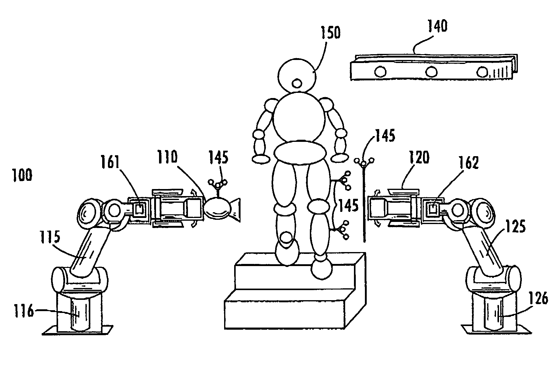
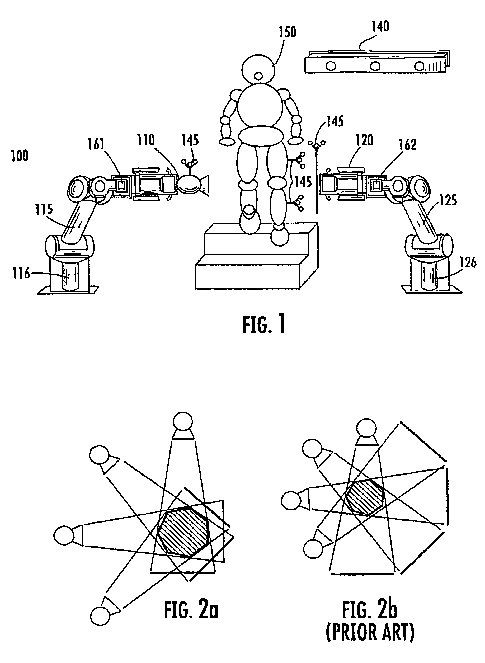
[0026]An imaging system 100 according to the invention is shown in FIG. 1 configured for dynamic as well as static imaging of the foot / ankle of patient 150. Although shown in FIG. 1 for foot / ankle measurements, system 100 can be used for dynamic radiographic imaging during natural activities such as walking, stair-climbing and lifting, and easy observation of other parts of the body of patient 150, such as the knee, hip, lumbar spine, cervical spine and shoulder.

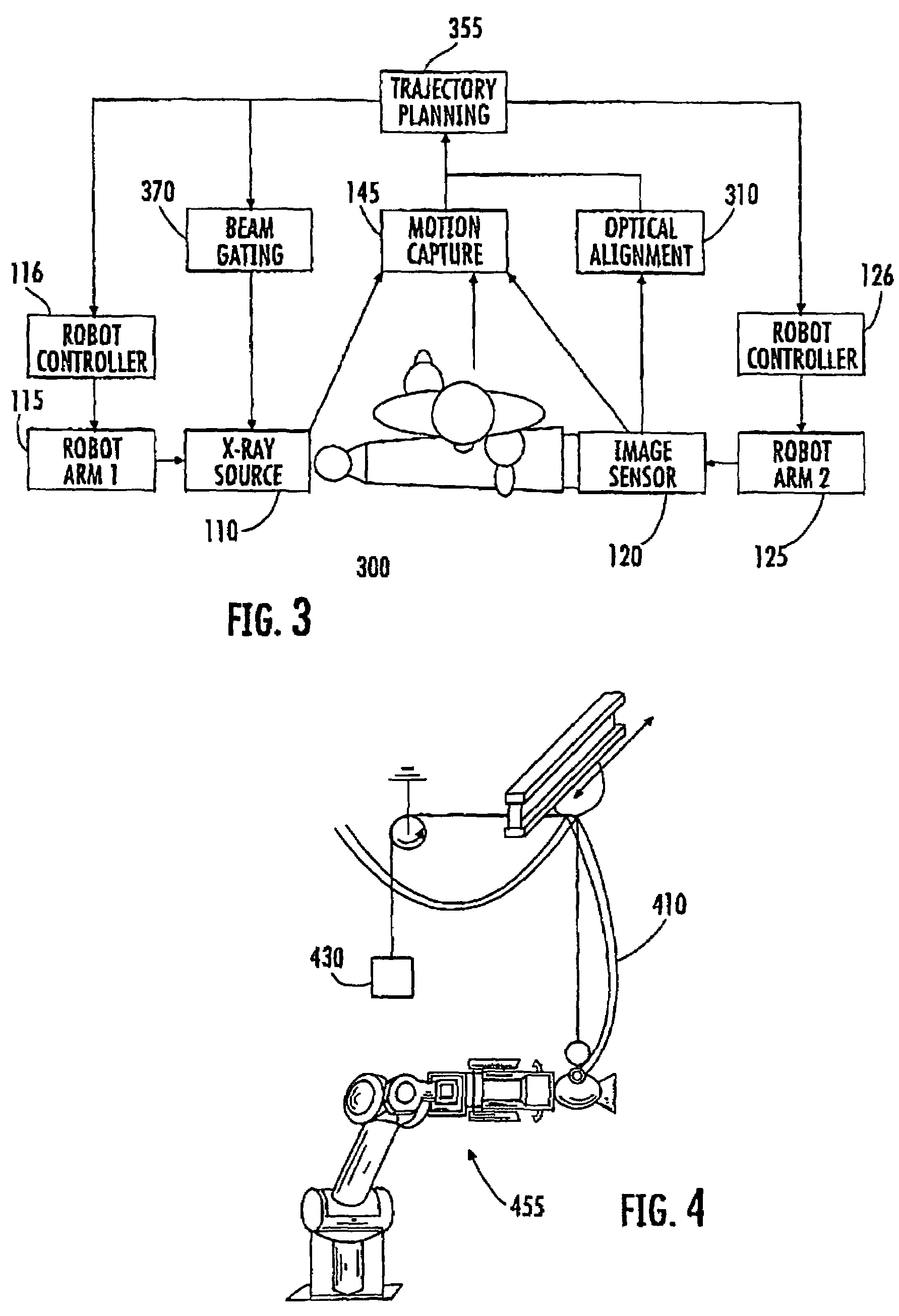
[0027]The imaging system 100 includes a penetrating radiation source 110 (e.g. x-ray) including a first translating device 115 comprising a position controller 116 for controlling the position of radiation source 110. A gating controller (not shown in FIG. 1) is provided for controlling the timing of emissions from source 110. Radiation detector 120 includes a second translating device 125 comprising a position controller for moving the detector 120. The radiation source 110 and detector 120 are aligned so that radiation fro...


PUM


Abstract

A radiographic imaging system includes (100) a penetrating radiation source (110) including a first translating device (115), the first translating device (115) comprising a first controller (116) for positioning the radiation source. A radiation detector (120) includes second translating device (125) comprising a second controller for positioning the detector (120). A motion capture device (140) is communicably connected to both the first and second controllers. The motion capture device (140) tracks a position of the subject being imaged and provides position information to both the first controller (116) and second controllers (126) for dynamically coordinating trajectories for both the radiation source (110) and the radiation detector(120). The first and second translating devices preferably comprise robotic arms.

Description

CROSS-REFERENCE TO RELATED APPLICATIONS[0001]This application is the national stage entry of International Application No. PCT / US2005 / 036390, filed Oct. 7, 2005, which claims priority to U.S. Provisional Application No. 60 / 616,945, filed Oct. 7, 2004.FIELD OF THE INVENTION[0002]The invention relates to radiographic medical imaging systems using a robotic Mounted source and sensor for dynamic image capture and tomography.BACKGROUND OF THE INVENTION[0003]Most major musculoskeletal impairments affect the mobile segments of the body, including the synovial (e.g. knees, hips and shoulder) and cartilaginous (e.g. spine, neck) joints. The mobility of these joints can increase or decrease with damage or disease: Osteoarthritis often results in loss of joint motion while ligament or capsular injury of the knee, hip or shoulder results in greater joint motion (laxity). In either case, characterizing joint motion is an important part of the diagnosis and an even more important part of the outc...

Claims


Application Information

Patent Timeline
Patent Type & Authority Patents(United States)
IPC IPC(8): H05G1/02
CPCA61B5/1038A61B5/1127A61B6/547G06T7/0042G06T7/2033A61B6/4452A61B6/4458A61B6/587A61B5/4528A61B6/447A61B6/4464G06T7/246G06T7/73
Inventor BANKS, SCOTT ARTHUR
Owner UNIV OF FLORIDA RES FOUNDATION INC
Why Eureka
Try Eureka