Horizontal axis wind turbine and idling method of the same

a horizontal axis wind turbine and idling technology, which is applied in the direction of rotors, marine propulsion, vessel construction, etc., can solve the problems of reducing the design strength of such a wind turbine, unable to achieve significant effect of reducing the load of blades, and unable to control pitch angle or the like until windstorm quiet down, etc., to achieve the effect of reducing the design load of blades in windstorm

Active Publication Date: 2008-11-04
HITACHI LTD
View PDF3 Cites 18 Cited by
  • Summary
  • Abstract
  • Description
  • Claims
  • Application Information

AI Technical Summary

Benefits of technology

[0017]A problem of the present invention is to provide a horizontal axis wind turbine capable of reducing design load of blade in windstorm.

Problems solved by technology

The design strength of such a wind turbine is greatly affected, for example, by a load caught in circumstances where the wind turbine is exposed to windstorm such as a typhoon.
However, controlling the direction of the rotor or a pitch angle as needed in response to change of the wind direction by yaw control, pitch angle control or the like until windstorm quiets down is not necessarily safe under a situation where electric power to be supplied for respective control systems is shut off, because the cases are expected where electric power supply for the area is shut off owing to blackout in windstorm.
However, there is a problem that a significant effect can not be obtained for reducing loads on blades while load on the top of the tower can be reduced in a horizontal axis wind turbine according to the above earlier development, as compared to the earlier upwind horizontal axis wind turbine, in windstorm.
Therefore, in view of profitability and costs, the development is not necessarily sufficient.

Method used


Image

  • Horizontal axis wind turbine and idling method of the same
  • Horizontal axis wind turbine and idling method of the same
  • Horizontal axis wind turbine and idling method of the same

Examples


example

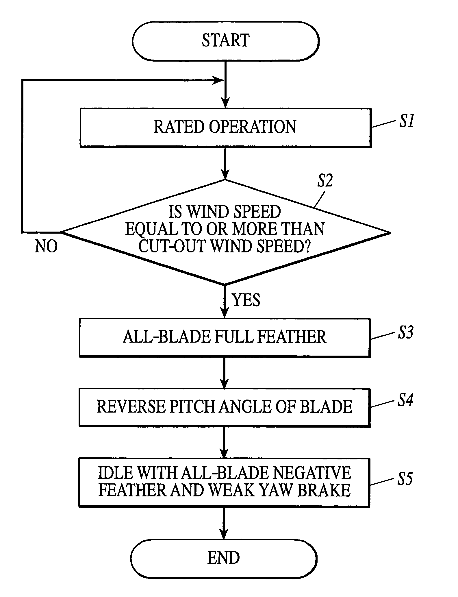
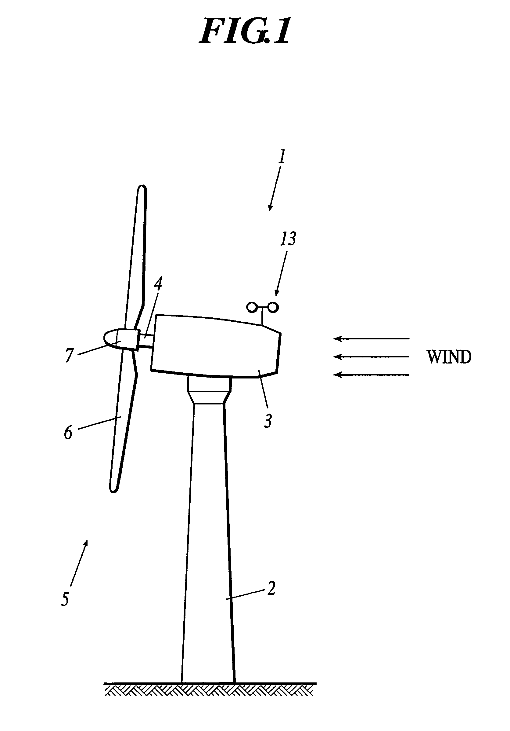
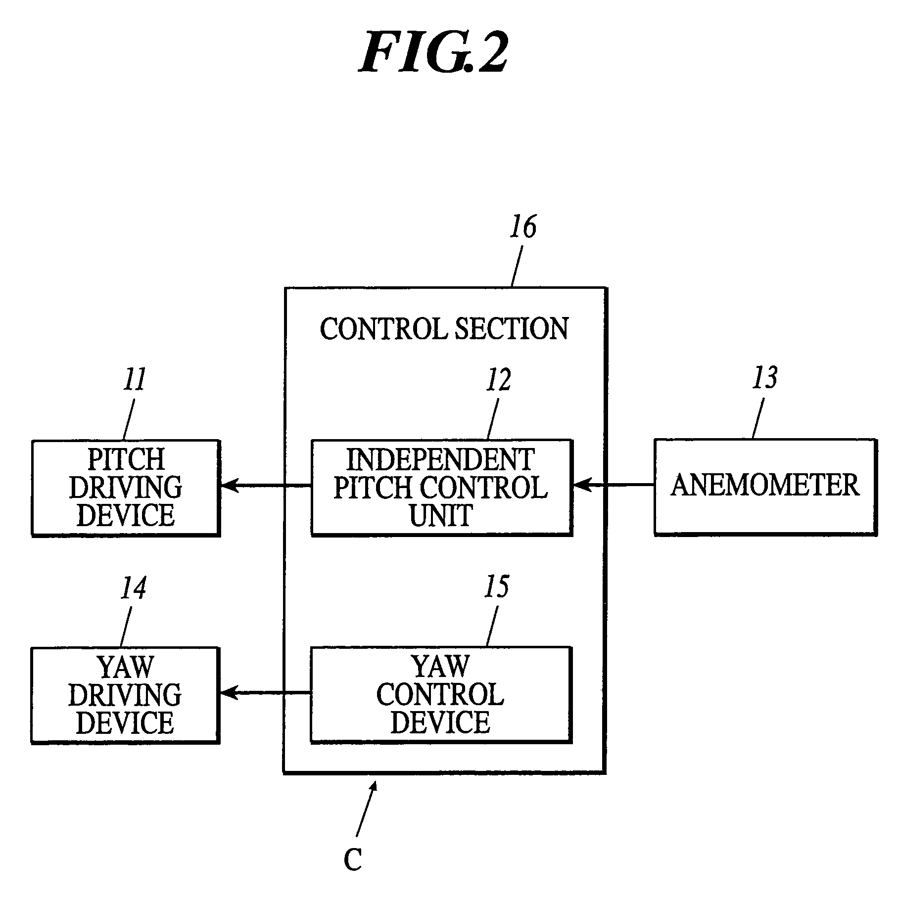
[0088]Next, examples embodying the present invention are described in detail with reference to the drawings. The present example shows the result of comparing the simulation result of the case (case No. (I)) of the following conditions: (1) the rotor position is a downwind type; (2) the yaw brake torque is 400 kNm; (3) the diameter of the rotor is 80 m; (4) the number of blade is three; (5) independent pitch control can be performed for each blade; and (6) the full feather pitch angle is 86 deg., and the wind direction / speed model of a fluctuating wind having an average wind speed of 50 m / sec shown in FIG. 3, with the case (case No. (II)) of an ordinary downwind type and having a pitch angle of −86 deg. (negative feather position) that is the same as the horizontal axis wind turbine comprising the independent pitch control unit and the case (case No. (III)) of a horizontal axis wind turbine that is an ordinary upwind type and comprises the independent pitch control unit. The summary...


PUM


Abstract

A horizontal axis wind turbine includes: a rotor having a hub and at least two or more blades; a nacelle for pivotally supporting the rotor through a rotating shaft connected to the hub; a tower for supporting the nacelle; and an independent pitch control unit capable of independently controlling pitch angles of the blades, respectively, wherein the independent pitch control units control the pitch angles so that all the blades are made in a full feather position in case of a wind speed not less than a predetermined value, and subsequently controls the pitch angles of the respective blades so as to be sequentially reversed one by one, and further subsequently, carries out control so that the wind turbine idles in an all-blade negative feather position where the pitch angles of all the blades are reversed.

Description

CROSS-REFERENCE TO RELATED APPLICATIONS[0001]The disclosure of Japanese Patent Application No. 2004-193271 filed on Jun. 30, 2004 including the specification drawing and abstract is incorporated herein by reference in its entirety.BACKGROUND OF THE INVENTION[0002]1. Field of the Invention[0003]The present invention relates to a horizontal axis wind turbine and an idling method of the same, and in particular, relates to a downwind horizontal axis wind turbine and an idling method of the same in windstorm.[0004]2. Description of Related Art[0005]While hitherto various kinds of wind turbines have been put into practical use for wind power generation, a representative example of general wind turbines that are commercially put into practical use is a horizontal axis wind turbine comprising: a rotor where at least two or more blades formed in such a way that the sectional shape of the blades is like a wing are radially attached to a hub; a nacelle that is connected to the hub and pivotall...

Claims


Application Information

Patent Timeline
Patent Type & Authority Patents(United States)
IPC IPC(8): F03D7/04F03D7/02
CPCF03D7/0212F03D7/0224F03D7/024F03D7/0264Y10S415/908F05B2270/32F05B2270/3201Y02E10/723Y02E10/72
Inventor YOSHIDA, SHIGEO
Owner HITACHI LTD
Why Eureka
Try Eureka