Fuel cell with helical structure

a fuel cell and helical structure technology, applied in the field of fuel cells, can solve the problems of short circuiting, deformation of the ion exchange membrane, and reducing the lifetime of the membrane and its associated elementary cells

Inactive Publication Date: 2008-11-04
COMMISSARIAT A LENERGIE ATOMIQUE ET AUX ENERGIES ALTERNATIVES
View PDF6 Cites 0 Cited by
  • Summary
  • Abstract
  • Description
  • Claims
  • Application Information

AI Technical Summary

Benefits of technology

[0024]Also, one advantage of the present invention lies in the increase, relative to the prior art, in the exchange surface area between the ion exchange membrane and the electrodes. While the parts contained in the prior art have substantially planar contact surfaces, the elementary cell of the invention has helical-type exchange surfaces which consequently generate growth of current density able to be produced.
[0025]Preferably, the ion exchange membrane has two threaded surfaces able to cooperate respectively with the threaded surfaces of the two electrodes, all these surfaces being made so that they have the same pitch.
[0026]Therefore it is possible to fabricate the ion exchange membrane using a film preformed to the pitch of the threaded surfaces of the two electrodes.
[0027]Preferably, one of the two electrodes consists of a coating deposited on a screw, and the other of the two electrodes consists of a coating deposited on a nut formed in a substrate.
[0028]With said configuration, provision can be made for the screw and substrate to be made in a porous material able to permit diffusion of the reagents in the direction of the electrodes. Also, the screw and substrate are respectively provided with at least one orifice in which at least one reagent may be injected.
[0029]According to one preferred embodiment of the present invention, the ion exchange membrane is carried by the electrode deposited on the screw, and each orifice provided in the substrate leads directly into a space delimited at least in part by the threaded surface of the electrode deposited on the nut, allowing the passage of each reagent in the interstices of a helical connection between the threaded surface of the electrode deposited on the nut and the ion exchange membrane.

Problems solved by technology

However, after conducting optical analyses under polarized light, it has been found that the clamping operation of the bipolar plates onto an elementary cell leads to deformations of the ion exchange membrane.
It is specified that when the clamping operation is completed and the elementary cell is held in position, the deformed parts of the membrane are blocked inside these channels, thereby considerably reducing the lifetime of this membrane and of its associated elementary cell.
In addition, when the elementary cell is in operation, it has also been noticed that the ion exchange membrane has a propensity to swell, causing rippling of those parts of the membrane positioned inside the channels of adjacent bipolar plates.
This generated rippling is found to contribute largely towards the onset of a major disadvantage, lying in the decreased contact surface area between this rippled membrane and the electrodes of the elementary cell, this decrease translating directly as a reduction in the ion exchange surface between these different parts.
The above-mentioned disadvantage therefore leads to the sole location of electrochemical activity in those membrane portions in contact with the electrodes, these portions consisting solely of the vertex of the ripples occurring at the time of membrane swelling.
Evidently, this highly specific locating of electrochemical activity causes accelerated ageing of the ion exchange membrane at the portions concerned, this localized ageing leading to the formation of cracks which may possibly cause short circuiting of the fuel cell, when the level of deterioration is such that the cracks have propagated to the point of leading into one another.
However, other observations made have also led to the conclusion that deformation of the gasket inevitably causes deformation of that part of the ion exchange membrane located close to this gasket.
Therefore it has been found that the square section shape chosen for the electrodes, membrane and bipolar plate is not at all suitable to allow the membrane to tolerate deformation of the gasket occurring during the clamping operation.
Consequently, the deformations of the membrane portions located close to the gasket also undergo accelerated ageing which may cause spontaneous formation of localized cracks on this membrane.

Method used


Image

  • Fuel cell with helical structure
  • Fuel cell with helical structure
  • Fuel cell with helical structure

Examples


Embodiment Construction

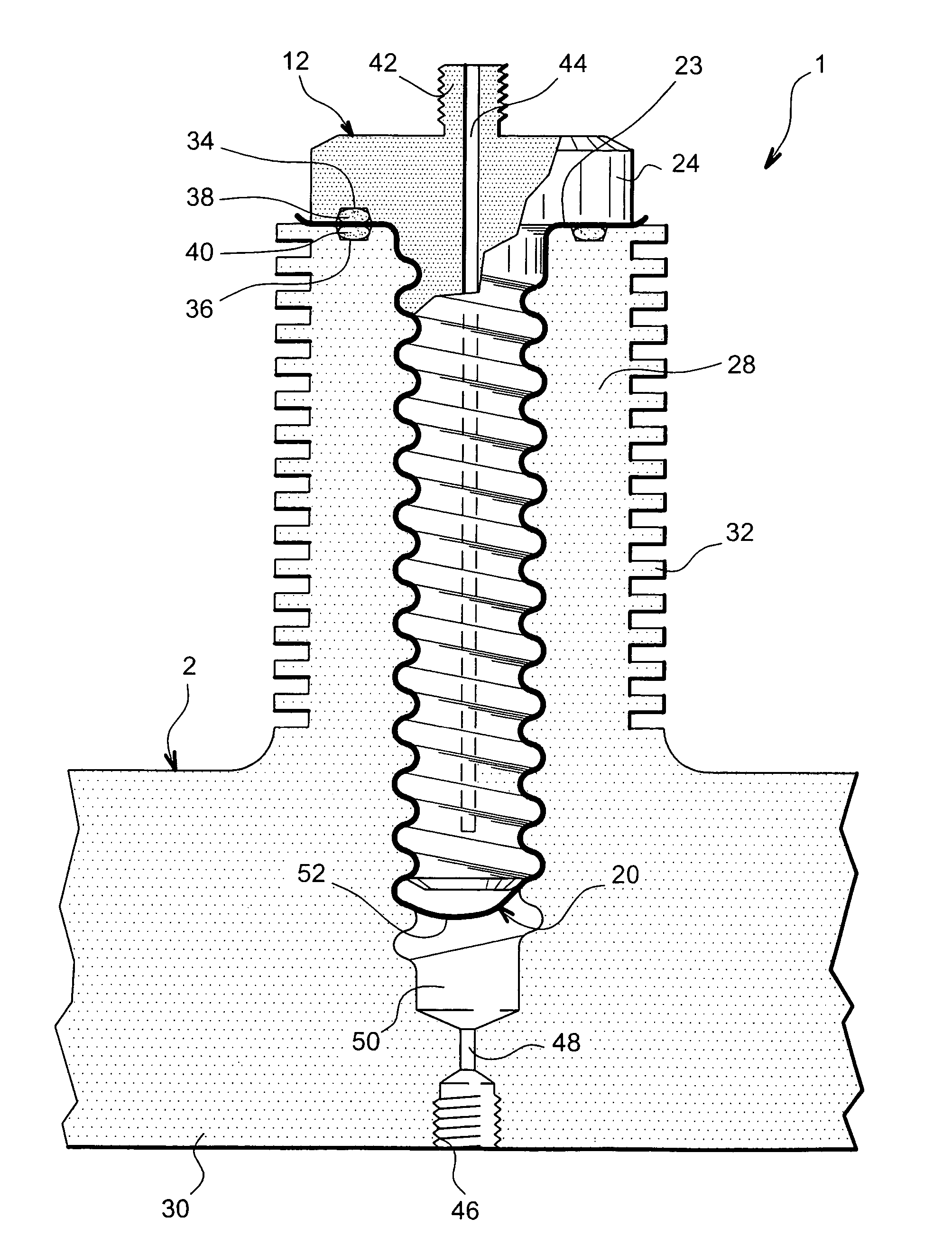
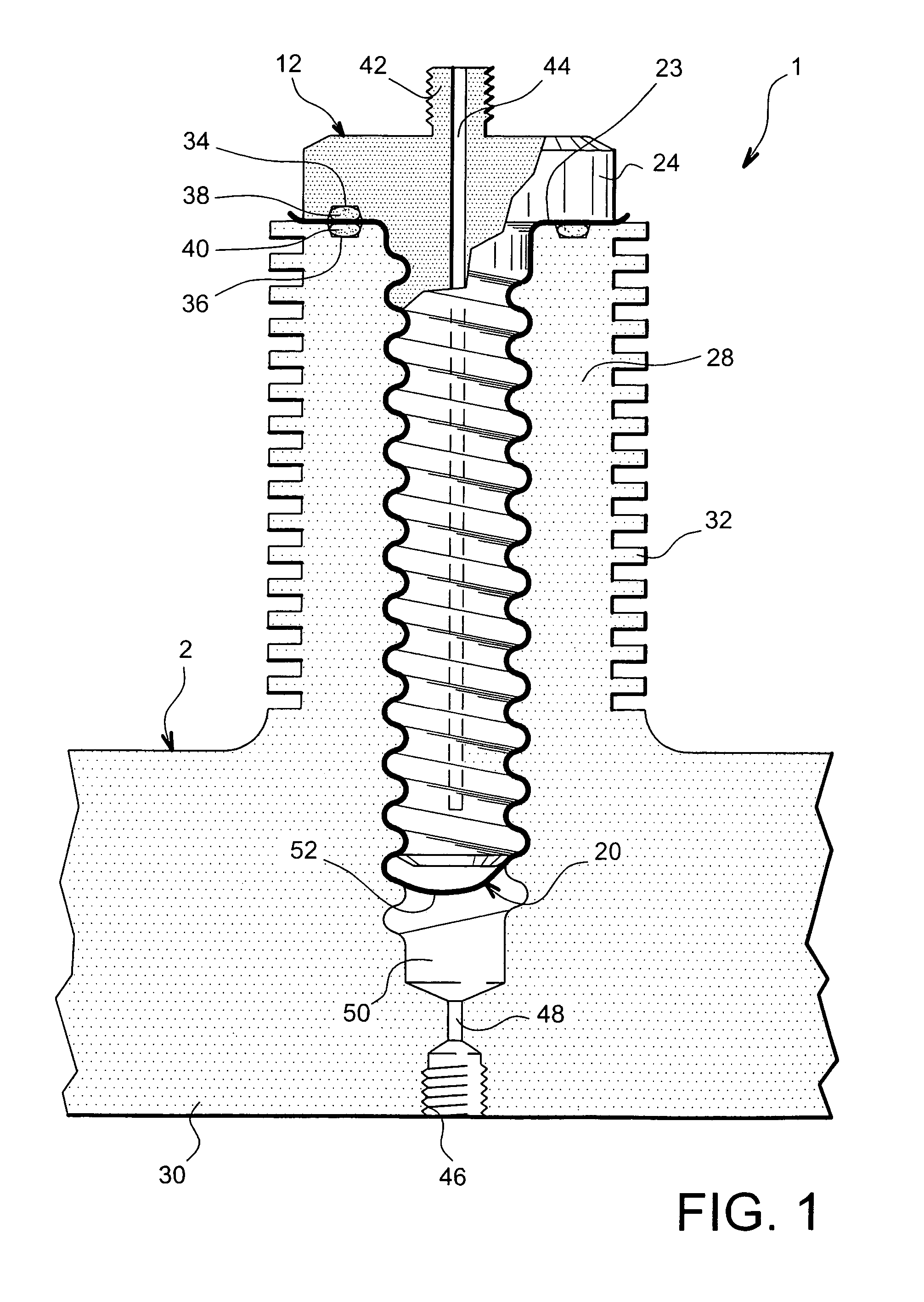
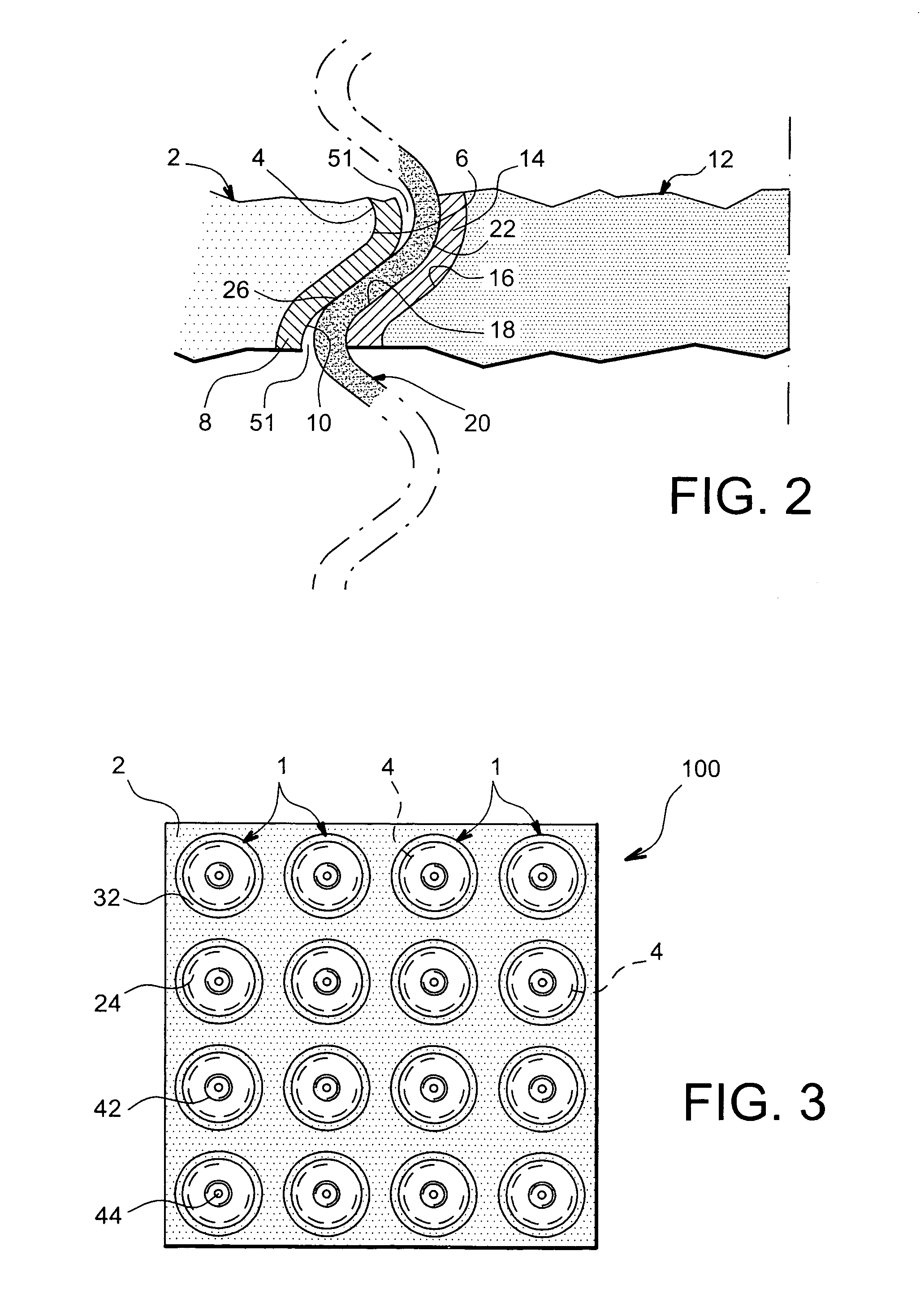
[0037]With reference to FIGS. 1 and 2, an elementary cell 1 can be seen for a fuel cell according to one preferred embodiment of the present invention.

[0038]Elementary cell 1, able for example to deliver a power of between 10 and 50 kW when forming part of medium-powered fuel cells, may be used in any type of fuel cell such as PEMFC cells nod DMFC cells.

[0039]Elementary cell 1 comprises a substrate 2 preferably made in porous material, in which a nut 4 is formed having a threaded surface 6.

[0040]A first electrode 8, preferably in graphite, silicon, ceramic or metal foam, is deposited in the form of a coating on threaded surface 6 of nut 4, and also has a threaded surface 10 of smaller diameter and identical pitch to threaded surface 6 of nut 4. The first electrode 8 may indifferently either extend over the entire height of threaded surface 6 of nut 4, or only on a portion of this threaded surface 6.

[0041]Elementary cell 1 also comprises a screw 12 preferably made in a porous materia...


PUM

PropertyMeasurementUnit
poweraaaaaaaaaa
poweraaaaaaaaaa
electrical energyaaaaaaaaaa

Abstract

The invention concerns an elementary cell (1) for a fuel cell comprising two electrodes between which an ion exchange membrane (20) is positioned. According to the invention, one of the two electrodes has a threaded surface carrying the ion exchange membrane (20), the assembly formed by this electrode and the ion exchange membrane (20) being able to be assembled by screwing onto a threaded surface belonging to the other of the two electrodes.The invention also concerns a fuel cell provided with a plurality of elementary cells (1).

Description

TECHNICAL FIELD[0001]The present invention relates to a fuel cell comprising as electrolyte a membrane of ion exchange type, and more specifically a proton exchange membrane.[0002]More particularly, the invention concerns elementary cells for fuel cells and their methods of manufacture, the elementary cells also called “electrode-membrane-electrode” assemblies conventionally comprising two electrodes between which the ion exchange membrane is positioned.[0003]By way of example, the invention finds application in the area of fuel cells of PEMFC-type (“Proton Exchange Membrane Fuel Cell), of DMFC-type (“Direct Methanol Fuel Cell”) or further of alkaline anion exchange type.PRIOR ART[0004]Generally, a fuel cell comprises a stack of elementary cells, inside which an electrochemical reaction takes place between two reagents added continuous fashion. The fuel, such as hydrogen for cells functioning with hydrogen / oxygen mixtures, or methanol for cells functioning with methanol / oxygen mixtu...

Claims


Application Information

Patent Timeline
Patent Type & Authority Patents(United States)
IPC IPC(8): H01M8/10H01M8/02H01M4/86
CPCH01M4/8605H01M8/1004Y02E60/521Y02E60/50Y02P70/50
Inventor TIQUET, PASCALMARSACQ, DIDIER
Owner COMMISSARIAT A LENERGIE ATOMIQUE ET AUX ENERGIES ALTERNATIVES
Why Eureka
Try Eureka