System for using digital signal processing to compensate for power compression of loudspeakers

a technology of digital signal processing and loudspeaker, applied in frequency response correction, heat measurement, instruments, etc., can solve the problems of heat generation and dissipation, transducer burn-up, limited power handling capacity of drivers, etc., to reduce the overall audio signal, reduce the cost of manufacturing the integrated system, and reduce the thermal resistance of voice coils

Active Publication Date: 2008-11-04
HARMAN INT IND INC
View PDF13 Cites 22 Cited by
  • Summary
  • Abstract
  • Description
  • Claims
  • Application Information

AI Technical Summary

Benefits of technology

[0010]A time-domain digital filter referred to as the cooling filter may model the reduction in voice coil thermal resistance due to a cooling effect. This cooling effect is produced from the movement of the voice coil in a certain frequency range. This cooling filter updates a thermal-modeling system, which in turn computes a temperature parameter. The temperature information may then be used to control respective equalizer/level adjusts (e.g. low, medium, and high frequencies equalizer/level adjusts) to compensate for power compression and uneven frequency response due to high voice coil temperatures. The temperature information can be used with a maximum coil temperature detector that controls a preamp to reduce the overall audio signal if the temperature of the coils is beyond an acceptable level.
[0011]Alternatively, the invention m

Problems solved by technology

One common problem associated with electromagnetic transducers is the generation and dissipation of heat.
Thus, the power handling capacity of a driver is limited by its ability to tolerate heat.
If more power is delivered to the transducer than it can handle, the transducer can burn up.
Another problem associated with he

Method used


Image

  • System for using digital signal processing to compensate for power compression of loudspeakers
  • System for using digital signal processing to compensate for power compression of loudspeakers
  • System for using digital signal processing to compensate for power compression of loudspeakers

Examples


Embodiment Construction

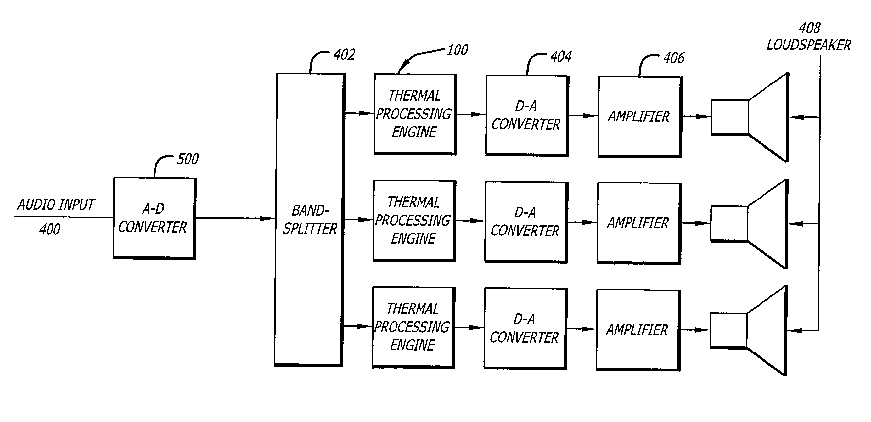
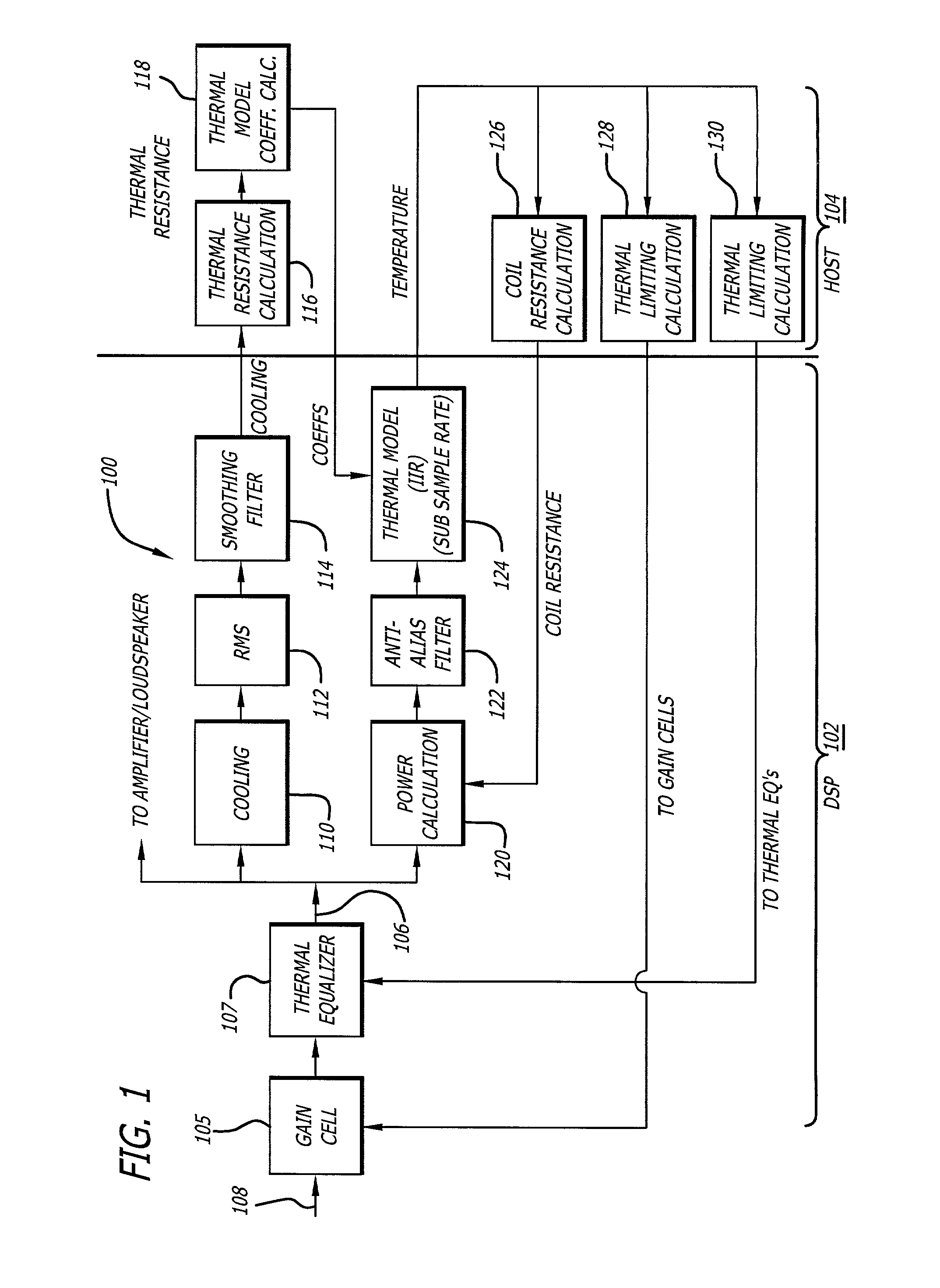
[0024]FIG. 1 illustrates a Thermal Processing Engine block diagram (TPE) 100 that compensates for loss of power due to the power compression effects of the loudspeaker as the temperature of the voice coil and the loudspeaker rises. To compensate for the power compression effect, the invention may predict or estimate the temperature of the voice coil using a thermal-model, and adjusting the estimated temperature accordingly due to the cooling effect as the voice coil moves back and forth in the air gap. The TPE 100 may be shared between a signal processor 102, such as a digital signal processor (DSP), and a host processor 104. The processing that does not need to be done at the audio sample rate may be run in the host processor 104 such as a general purpose micro-controller, where a better floating point math and a better development environment may be available.

[0025]On the input side 108, the signal passes through a Gain Cell 105 and then a Thermal Equalizer 107, both of which woul...


PUM


Abstract

This invention provides a compensation system capable of compensating for power loss due to the power compression effects of the voice coil as the temperature of the voice coil increases. To compensate for the power compression effect, the invention predicts or estimates the temperature of the voice coil using a thermal-model, and adjusts the estimated temperature according to the cooling effect as the voice coil moves back and forth in the air gap. The thermal-model may be an equivalent electrical circuit that models the thermal circuit of a loudspeaker. With the input signal equating to the voltage delivered to the loudspeaker, the thermal-model estimates a temperature of the voice coil. The estimated temperature is then used to modify equalization parameters. To account for the cooling effect of the moving voice coil, the thermal resistance values may be modified dynamically, but since this cooling effect changes with frequency, a cooling equalization filter may be used to spectrally shape the cooling signal, whose RMS level may be used to modify the thermal resistance values. The invention may include a thermal limiter that determines whether the estimated voice coil temperature is below a predetermined maximum temperature to prevent overheating and possible destruction of the voice coil.

Description

CROSS-REFERENCES TO RELATED APPLICATIONS[0001]This application is a non-provisional application claiming priority of U.S. Provisional Patent Application Serial No. 60 / 231,721 filed Sep. 8, 2000.BACKGROUND OF THE INVENTION[0002]1. Field of the Invention[0003]This invention relates to a system that predicts the temperature of the voice coil in a loudspeaker using a thermal-model, and then using that information to perform appropriate compensation of the audio signal to reduce power compression and provide a desired frequency response across a desired bandwidth.[0004]2. Related Art[0005]An electromagnetic loudspeaker (transducer, motor, or driver) uses magnets to produce magnetic flux in an air gap. These magnets are typically permanent magnets, used in a magnetic circuit of ferromagnetic material to direct most of the flux produced by the permanent magnet through the components of the motor and into the air gap. A voice coil is placed in the air gap with its conductors wound cylindric...

Claims


Application Information

Patent Timeline
IPC IPC(8): H03G11/00H04R1/00H04R29/00H04R3/00H04R3/04
CPCH04R3/00H04R3/04H04R29/003G01K7/427
Inventor BUTTON, DOUGLAS J.WILLIAMS, PAUL ROBERT
Owner HARMAN INT IND INC
Why Eureka
Try Eureka