Terminal connecting apparatus

a technology of connecting apparatus and terminal, which is applied in the direction of fixed connection, connection formation by deformation, manufacturing tools, etc., can solve the problems of product generation, lower reliability of connection between terminal and conductor, etc., and achieve the effect of preventing damage, maximizing the width of pressing member, and improving product quality

Inactive Publication Date: 2008-11-11
YAZAKI CORP
View PDF6 Cites 2 Cited by
  • Summary
  • Abstract
  • Description
  • Claims
  • Application Information

AI Technical Summary

Benefits of technology

[0016]According to the terminal connecting apparatus as mentioned above, front ends of the projections provided at the guide walls are contact points against the terminal. When the width between the pair of guide walls is larger than that of the terminal, making a width between the contact points narrower than that of the terminal by providing the projections, the gap generated between the terminal and guide walls can be absorbed. Thereby, terminal connecting can be acted accurately and dispersion of product quality can be improved.
[0017]According to the terminal connecting apparatus as mentioned above, the front ends of the projections provided at the guide walls are contact points against the terminal. Thereby, the width between the pair of guide walls can be designed wider than the width of the terminal, and a width of the pressing member sliding between the pair of guide walls can be designed to increase up to the width between the pair of guide walls. In the terminal connecting apparatus for joining a narrow width terminal, the width of the pressing member can be maximized for maintaining enough strength, so that the pressing member can be prevented from damage.
[0018]A part of the claw of the terminal penetrating through the conductor of the flat circuit body is removed by the projection, so that a fresh surface of the claw is generated, and by making contact between the fresh surface and a broken surface of the conductor by the claw penetrating therethrough, conductivity therebetween can be enhanced. Since the part of the claw is removed by the projection, contact area of the terminal and the conductor is increased so that conductivity therebetween can be more enhanced.
[0019]According to the terminal connecting apparatus, the projecting length of the projection can be changed by the adjusting mechanism, so that various terminal shaving different dimensions can be applied to the same apparatus.

Problems solved by technology

Thereby, reliability of the connection of the terminal and the conductor would be lower, or defective products may be generated, and product quality is dispersed widely.

Method used


Image

  • Terminal connecting apparatus
  • Terminal connecting apparatus
  • Terminal connecting apparatus

Examples


Embodiment Construction

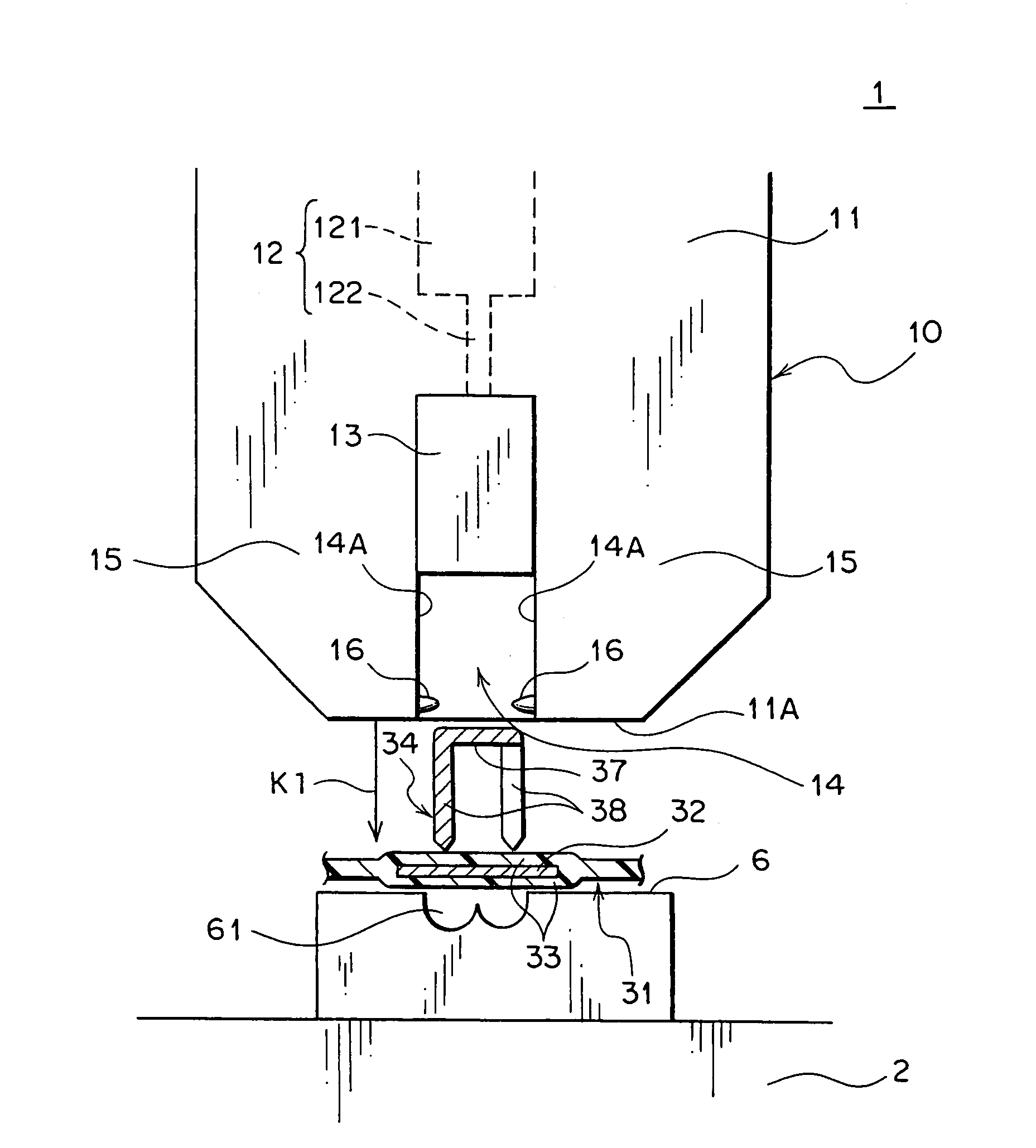
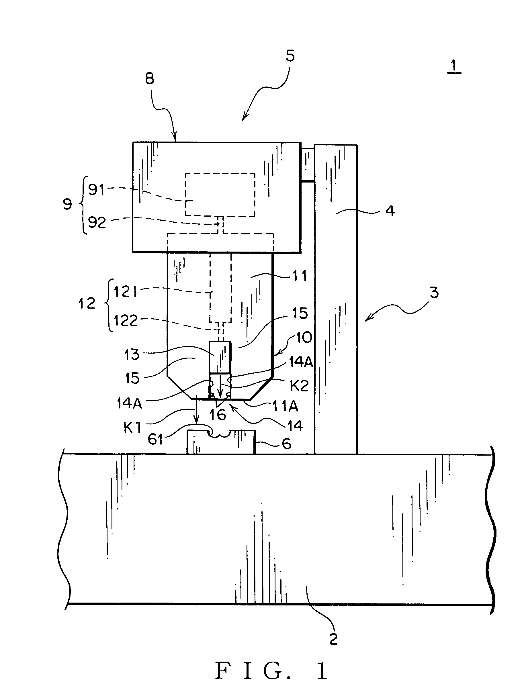
[0029]A terminal connecting apparatus of an embodiment according to the present invention will be described with reference to FIGS. 1-6. A flat circuit body described in this specification means an electric wiring product formed into a flat-band shape as a whole by covering a flat conductor with an insulation cover, such as an FPC (Flexible Printed Circuit) and an FFC (Flexible Flat Cable).

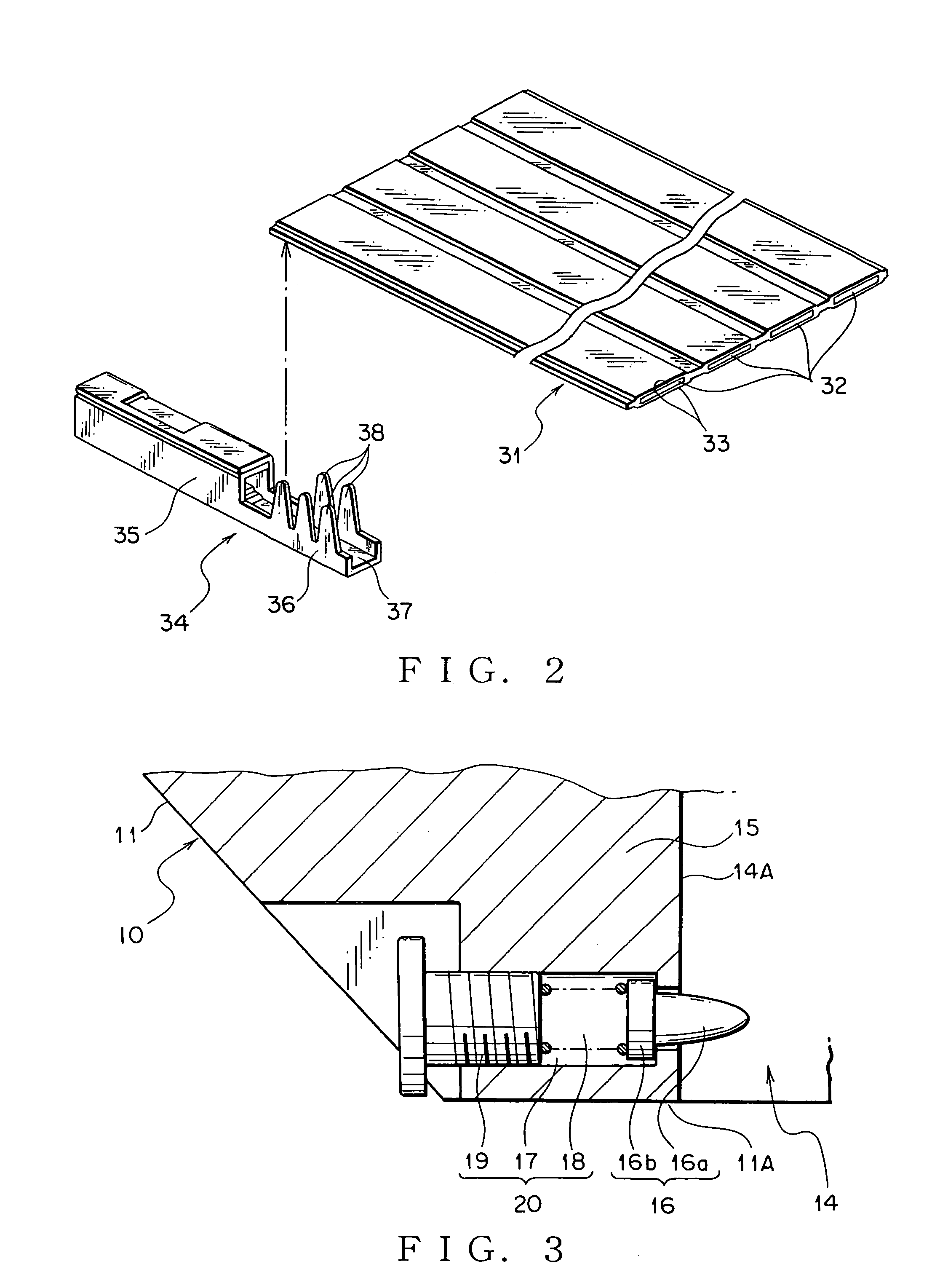
[0030]A terminal connecting apparatus 1 shown in FIG. 1 is for joining a terminal 34 shown in FIG. 2 with an FFC 31 as the flat circuit body shown in FIG. 2. The FFC 31 is a flat cable formed by arranging flat conductors 32 in parallel and covering both surfaces of the conductors 32 with an insulation cover 33 such as a polyester tape.

[0031]The terminal 34 is made of a sheet metal, which is plated with tin on surfaces of a base metal such as brass. The terminal 34 has an electric contact portion 35 to be connected with a mating terminal and a wire joining portion 36 to be joined with the FFC 31. T...


PUM

PropertyMeasurementUnit
lengthaaaaaaaaaa
flexibleaaaaaaaaaa
electric poweraaaaaaaaaa

Abstract

Providing a terminal connecting apparatus for improving accuracy of connecting a terminal to a flat circuit body, an applicator main body includes a pair of guide walls for placing and positioning a terminal therebetween so as to arrange front ends of the claws of the terminal opposing toward an FFC and projections projecting respectively from surfaces opposing to each other of the pair of guide walls. When the applicator main body approaches the terminal mounted on the receiving base, the projections slide on outer surfaces of the claws of the terminal and remove parts of plated layers formed on the outer surfaces of the claws. Fresh surfaces of the claws and fresh broken surfaces of the conductor by the claws penetrating therethrough are connected electrically.

Description

[0001]The priority application Number Japan Patent Application 2005-249118 upon which this patent application is based is hereby incorporated by reference.BACKGROUND OF THE INVENTION[0002]1. Field of the Invention[0003]This invention relates to a terminal connecting apparatus for connecting a terminal to a conductor of a flexible flat circuit body, such as an FPC (Flexible Printed Circuit), an FFC (Flexible Flat Cable).[0004]2. Description of the Related Art[0005]Many various electronic devices are installed in a car as a vehicle. A wiring harness is wired in the car for transmitting electric power and control signals to the electronic devices. The wiring harness includes a plurality of electric wires and a plurality of connectors. The electric wire is a covered wire including a conductive core wire and an insulation cover for covering the core wire.[0006]The connector includes an insulation housing fitting into a mating housing of a mating connector and a conductive terminal to be ...

Claims


Application Information

Patent Timeline
Patent Type & Authority Patents(United States)
IPC IPC(8): H01R12/38H01R43/048H01R43/058
CPCH01R4/182H01R12/68H01R43/05Y10T29/53209Y10T29/53235Y10T29/53213Y10T29/49174Y10T29/532Y10T29/49188Y10T29/5193
Inventor KUMAKURA, HIDETO
Owner YAZAKI CORP
Why Eureka
Try Eureka