Pad type plunger

a plunger and pad type technology, applied in the direction of fluid removal, positive displacement liquid engine, borehole/well accessories, etc., can solve the problems of large cost, gap in the coupling of all threaded production strings, and the inside surface of such production strings is not perfect, so as to reduce or control the effect of swabbing, reducing the effect of difficulty

Active Publication Date: 2008-11-11
ENDURANCE ELEVATOR SOLUTIONS LLC
View PDF15 Cites 12 Cited by
  • Summary
  • Abstract
  • Description
  • Claims
  • Application Information

AI Technical Summary

Benefits of technology

[0007]The plunger of this invention comprises a mandrel or body having one or more rigid pads on the exterior that are biased outwardly into engagement with the inner surface of a production string by the pressure differential that drives the plunger upwardly. The pads provide a seal of increased effectiveness to more efficiently lift liquids in the production string. The word “seal” is used even though it is somewhat of a misnomer because the real purpose of the seal is to reduce or control, rather than prevent, the amount of liquid and gas bypassing around the plunger. Several embodiments of this invention are disclosed, including a two piece plunger, a one piece plunger, and a spring assisted pad.

Problems solved by technology

Two phase upward flow in a well is a complicated affair and most engineering equations thought to predict two phase flow are only rough estimates of what is actually occurring.
If flow stops, the well has to be swabbed, at considerable expense, to bring it back on production.
The inside surface of such production strings is not a perfect cylinder for a variety of reasons.
First, there is a gap in the coupling of all threaded production strings where liquid collects and is bypassed by the plunger or piston.
Second, no production string has a perfect inside surface when new and, manifestly, much used tubing with all its imperfections is run in new shallow wells.
Third, during use there is sometimes a buildup of minerals on the inside surface.
Fourth, corrosion can cause buildup on the inside surface or erosion of the inside surface, depending on the type of corrosion.
Fifth, there are other mechanisms at work to erode the inside surface, such as high volume sand-laden production when a well is being cleaned up after a frac job.
Sixth, production pipe can become egg shaped because of handling or mishandling during transportation or when being run into a well.
Attempting to use a larger diameter plunger creates too great a risk of sticking the plunger in the production string.

Method used


Image

  • Pad type plunger
  • Pad type plunger
  • Pad type plunger

Examples


Embodiment Construction

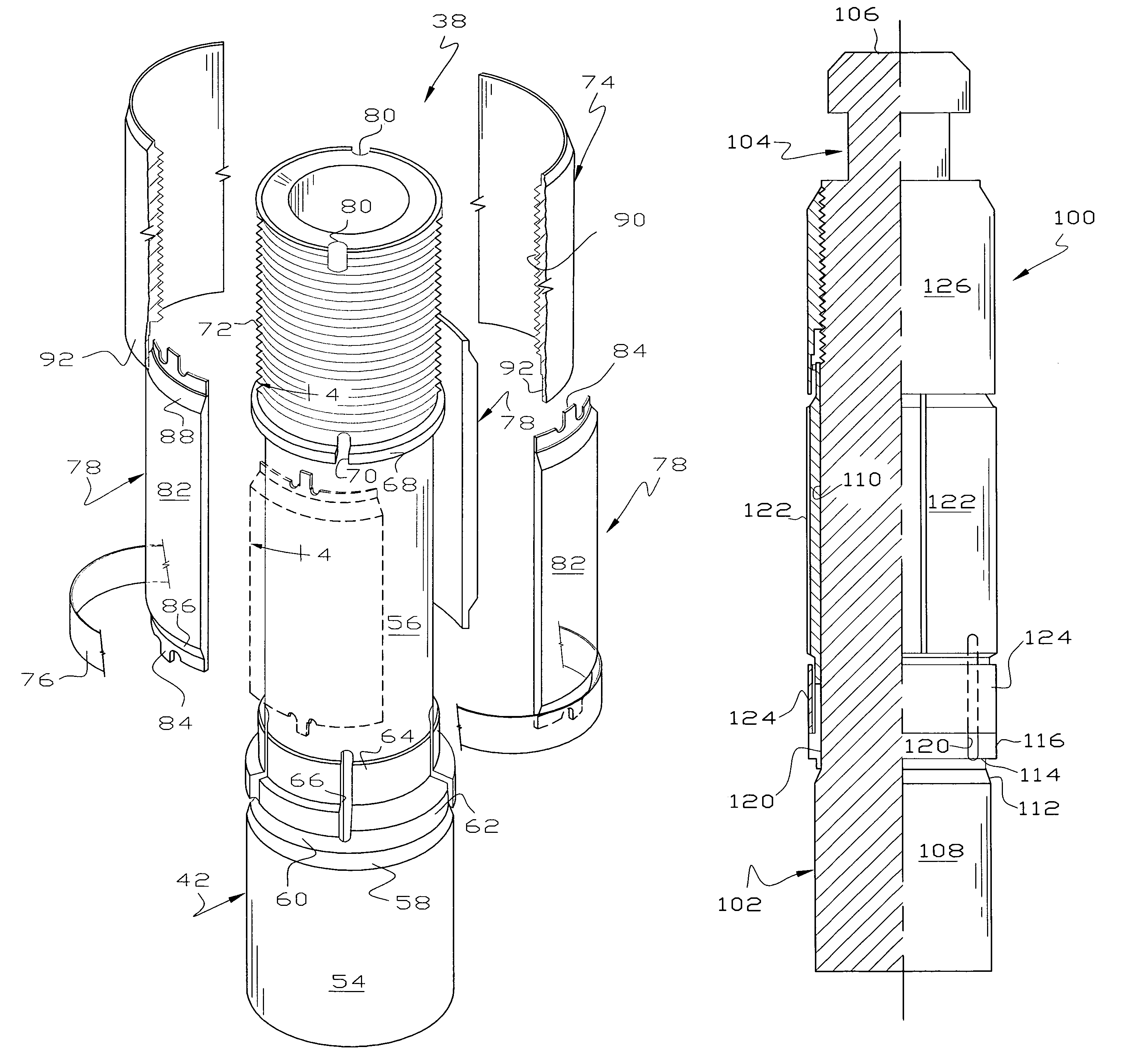
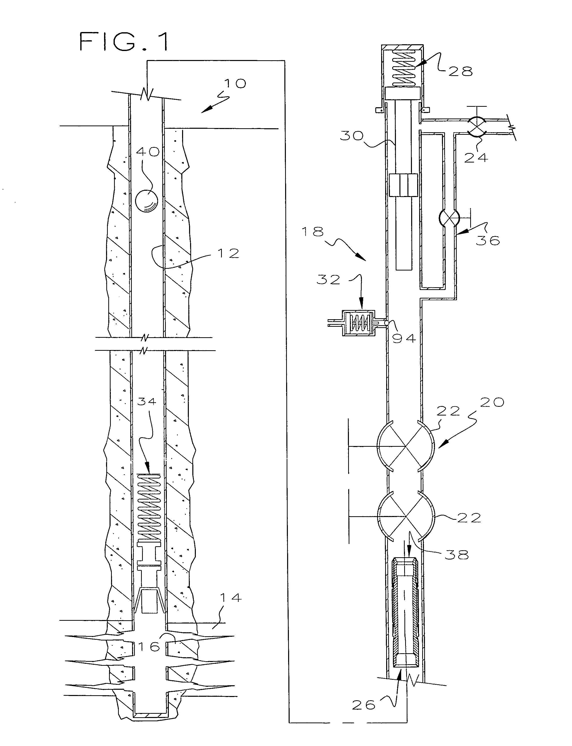
[0020]Referring to FIGS. 1-4, a hydrocarbon well 10 comprises a production string 12 extending into the earth in communication with a subterranean hydrocarbon bearing formation 14. The production string 12 is typically a conventional tubing string made up of joints of tubing that are threaded together. Although the production string 12 may be inside a casing string (not shown), it is illustrated as cemented in the earth. The formation 14 communicates with the inside of the production string 12 through perforations 16. A plunger lift 18 may be used to lift oil, condensate or water from the bottom of the well 10 which may be classified as either an oil well or a gas well.

[0021]In a typical application of this invention, the well 10 is a gas well that produces some formation liquid. In an earlier stage of the productive life of the well 10, there is sufficient gas being produced to deliver the formation liquids to the surface without artificial lift equipment. The well 10 is equipped w...


PUM


Abstract

A plunger lift for a hydrocarbon well includes a piston that is dropped into the well and then moved upwardly to lift liquid to the surface from adjacent a hydrocarbon formation. The piston includes a series of pads biased outwardly into engagement with an inside wall of the production string thereby providing an improved seal between the piston and the production string. The pads are biased outwardly by pressure from below or a pressure differential that is moving the piston upwardly. The force moving the pads outwardly are greater during upward movement of the piston than during downward movement. The piston includes a central one-piece mandrel having an upper end higher than any component of the piston and a lower end lower than any component of the piston so that impact forces are applied directly to the mandrel and not through a threaded component.

Description

[0001]This invention relates to a plunger lift and more particularly to a pad type plunger for moving liquids upwardly in a hydrocarbon well and more specifically to an improved technique for sealing between the exterior of the plunger and the inside of the production string.BACKGROUND OF THE INVENTION[0002]Because of the improvements provided by two piece plungers, plunger lifts have become considerably more common in hydrocarbon wells, particularly in lifting water and condensate from gas wells. A fast growing segment of artificial lift equipment is the use of plungers that lift sufficient liquids to keep otherwise marginal gas wells producing. Of course, high oil and gas prices contribute to the desire to keep older wells producing and two piece plunger lift systems have been effective in this regard. Typical two piece plunger lift systems are shown in U.S. Pat. Nos. 2,001,012 and 6,467,541.[0003]Gas wells reach their economic limit for a variety of reasons. A common reason is th...

Claims


Application Information

Patent Timeline
Patent Type & Authority Patents(United States)
IPC IPC(8): E21B43/16E21B33/10
CPCE21B43/121
Inventor WELLS, EDWARD A.
Owner ENDURANCE ELEVATOR SOLUTIONS LLC
Why Eureka
Try Eureka