Roll bonding of bipolar plates

a bipolar plate and roll bonding technology, applied in the direction of solventing apparatus, manufacturing tools, electrochemical generators, etc., can solve the problems of enlarge, thin sheets, complex and expensive manufacture of such bipolar plates, etc., and achieve the effect of increasing the bonding strength of the roll bonding interfa

Active Publication Date: 2008-11-18
GM GLOBAL TECH OPERATIONS LLC
View PDF15 Cites 9 Cited by
  • Summary
  • Abstract
  • Description
  • Claims
  • Application Information

AI Technical Summary

Benefits of technology

[0007]Sheet metal material is selected for the bipolar plate application, such as thin gage 316L stainless steel. Designs for the respective fuel and oxidant flow passages on separate sheets are made with the understanding that the opposite sides of these flow passages will serve as coolant flow passages between the joined sheets. A soft metal bonding material, such as particles of aluminum, is selected for joining the sheets of the bipolar plate. The aluminum particles may contain small amounts of impurities or alloying elements but they are to be softer than the plate material and inexpensive. Aluminum is also known to be chemically reactive with respect to ferrous alloys. Under the energy of roll bonding, aluminum atoms in the strategically placed, deformed particles can react with the iron-containing surfaces pressed on them to form intermetallic compounds that increase bonding strength of the roll bonded interface.
[0009]Following application of the soft metal bonding material, facing sheets are passed between rollers that press the sheets over the patterned area. The rolling pressure is sufficient to deform the soft particles into intimate bonding contact at selected locations between the facing sheets. But a purpose of using the soft metal bonding material is to deform it without excessive deformation of the bipolar sheets. And, as stated, when the soft material is suitably reactive with the facing sheet material additional chemical bonding may occur.

Problems solved by technology

The manufacture of such bipolar plates has been complex and expensive.
This practice is somewhat simpler than stamping, aligning, and brazing the sheets, but the roll bonding tends to significantly thin the sheets and enlarge their area, and allowance must be made to achieve the desired shape of the bipolar plate for fitting into the fuel cell stack.

Method used


Image

  • Roll bonding of bipolar plates
  • Roll bonding of bipolar plates
  • Roll bonding of bipolar plates

Examples


Embodiment Construction

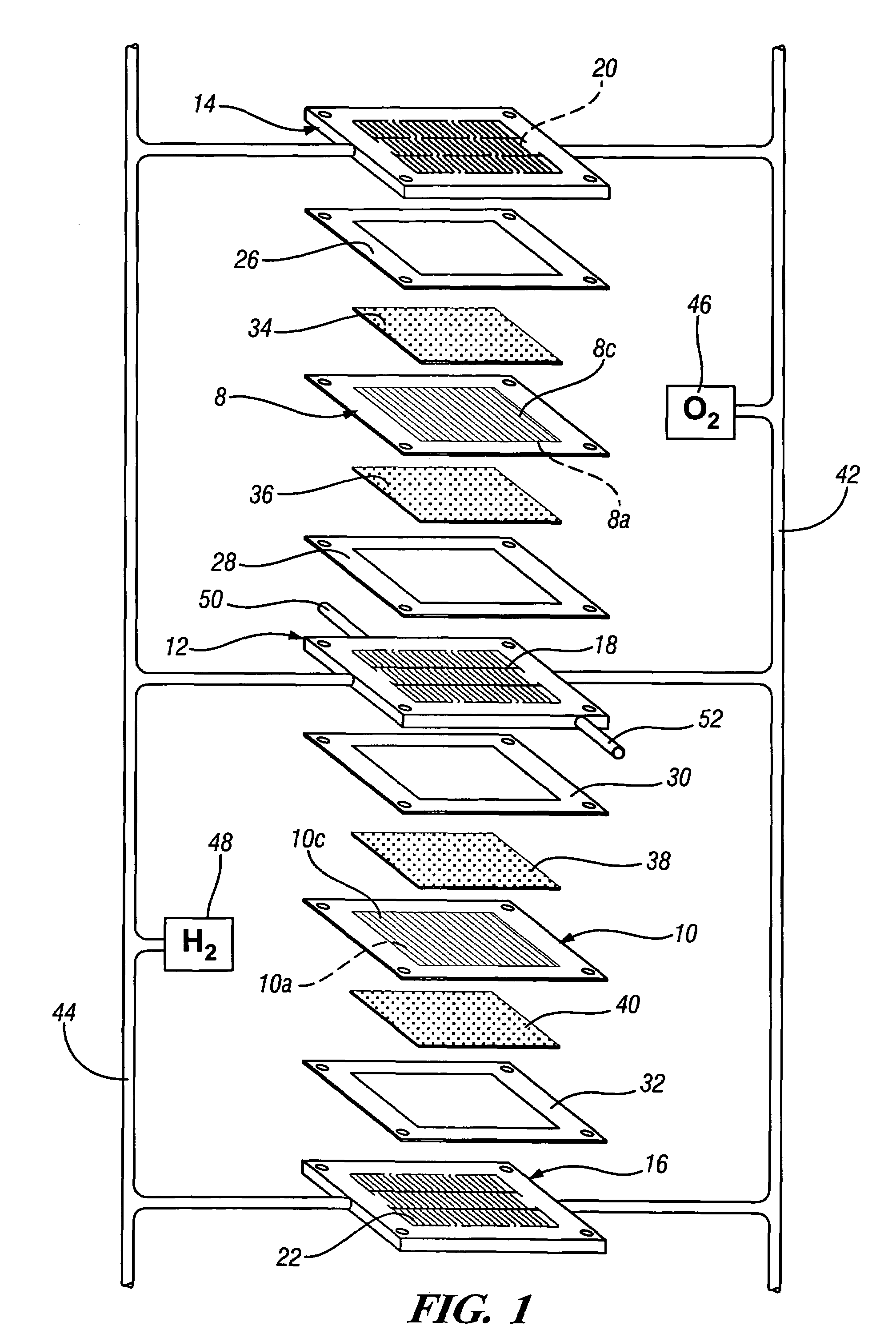
[0020]FIG. 1 schematically depicts a representative partial fuel cell stack having a pair of membrane-electrode-assemblies (MEAs) 8 and 10 separated from each other by a non-porous, electrically-conductive bipolar plate 12. Each of the MEAs 8, 10 have a cathode face 8c, 10c and an anode face 8a, 10a. The MEAs 8 and 10, and bipolar plate 12, are stacked together between non-porous, electrically-conductive, liquid-cooled bipolar plates 14 and 16. The bipolar plates 12, 14 and 16 each include flow fields 18, 20 and 22 having a plurality of flow channels formed in the faces of the plates for distributing fuel and oxidant gases (e.g., H2 and O2) to the reactive faces of the MEAs 8 and 10. Nonconductive gaskets or seals 26, 28, 30 and 32 provide a seal and electrical insulation between the several plates of the fuel cell stack.

[0021]Porous, gas permeable, electrically conductive sheets 34, 36, 38 and 40 press up against the electrode faces of the MEAs 8 and 10 and serve as primary current...


PUM

PropertyMeasurementUnit
metallicaaaaaaaaaa
pressureaaaaaaaaaa
conductiveaaaaaaaaaa

Abstract

A current collector plate, also called a bipolar plate, for a fuel cell includes two facing metal sheets with fluid channels for the fuel (often hydrogen) on the non-facing side of one sheet and fluid channels for air on the non-facing side of the other sheet. Such a plate is made by applying a patterned coating of particles of a soft and reactive metal to at least one of the sheets and rolling them together so that the soft metal particles deform and interact with the facing sheets to selectively join them at the patterned areas. Pressurized fluid is introduced between the sheets to expand non-bonded portions and define the fluid channels.

Description

TECHNICAL FIELD[0001]This invention pertains to the manufacture of pairs of joined bipolar plates that are shaped to define a pattern of fluid flow channels on their external and facing surfaces. More specifically, this invention pertains to the use of a relatively soft conductive material in roll bonding selected portions of the plates before expanding portions to produce the flow channels.BACKGROUND OF THE INVENTION[0002]Fuel cells that electrochemically combine hydrogen and oxygen are presently being developed and used for production of electric power in stationary and automotive applications. These power sources are assemblies of a stack of individual cell elements to deliver a power requirement at a specified voltage. The heart of a cell is a membrane electrolyte and electrode assembly (MEA) comprising, for example, a solid polymer, proton exchange electrolyte membrane with a porous catalytic anode on one side of the electrolyte membrane and a porous catalytic cathode on the ot...

Claims


Application Information

Patent Timeline
Patent Type & Authority Patents(United States)
IPC IPC(8): B23K31/02
CPCB23K20/02H01M8/0206H01M8/021H01M8/0282H01M8/0297B23K2201/16B23K2203/04B23K2203/10H01M8/0254Y02E60/50B23K2101/16B23K2103/05B23K2103/10H01M8/0258H01M8/0263H01M8/241
Inventor SIGLER, DAVID R.GAYDEN, XIAOHONGCHEN, YEN-LUNG
Owner GM GLOBAL TECH OPERATIONS LLC
Why Eureka
Try Eureka