X-ray device with an x-ray source fixed to a ceiling stand

a technology of x-ray source and x-ray device, which is applied in the field of x-ray device, can solve the problems of patients or staff suffering injuries, interference with the positioning of the x-ray source, and disadvantages of conventional x-ray device in many respects, and achieve the effect of reducing the length of the electrical connection path between the generator and the x-ray source and reducing certain capacitative effects

Inactive Publication Date: 2008-11-18
SIEMENS HEALTHCARE GMBH
View PDF7 Cites 5 Cited by
  • Summary
  • Abstract
  • Description
  • Claims
  • Application Information

AI Technical Summary

Benefits of technology

[0005]An object of the invention is to eliminate the disadvantages according to the prior art. In particular, an x-ray device is to be specified which can be assembled in the most simple and cost-effective way possible, and which can be operated with a reduced risk of injury. According to a further aim of the invention, the proposed x-ray device is to enable a lowest possible dose to be applied.
[0007]Provision is made in accordance with the invention for a conductor rail to be provided on the guide rail and at least one sliding contact interacting with the conductor rail is provided on the ceiling stand so as to produce an electrical connection with the x-ray source. The conductor rail provided according to the invention and the sliding contact interacting therewith allow the conventional long high-voltage cable provided for producing an electrical connection between the generator and the x-ray tube to be dispensed with. The x-ray source can be advantageously moved without any great force. In particular, drives used to assist with a movement of the x-ray facility need not be provided. At the same time, the risk of injury caused with a movement of the x-ray tube by means of the tooing and froing of the high-voltage cable is obviated. The conductor rail can be designed to be comparatively significantly shorter than the conventional high-voltage cable so as to ensure an adequate freedom of movement of the x-ray tube. Consequently, it is possible to reduce an applied dose. Finally, the provision of a conductor rail and a sliding contact interacting therewith enables the x-ray device to be assembled in a simpler manner.
[0011]According to a further particularly advantageous embodiment, the generator comprises means for suspended fixing to a ceiling. If the generator is fixed in a suspended manner, it can be fixed in the vicinity of the guide rail. Once again, the length of the electrical connecting path between the generator and the x-ray source can be shortened. As a consequence, certain capacitative effects can thus be further reduced by means of the length of the conductor.

Problems solved by technology

The conventional x-ray device is disadvantageous in many respects.
The high-voltage cable suspended from the ceiling in loops can interfere with a positioning of the x-ray source.
Aside from this, an injudicious movement of the x-ray tube can even lead to patients or staff sustaining injuries.
The provision of the relatively stiff high-voltage cable renders the x-ray source moveable only with a relatively significant amount of effort.
The assembly of the high-voltage cable is complex and expensive.
Finally, the conventional relatively long high-voltage cable has a capacitance which cannot be ignored, which results in an unwanted current flow and thus x-ray generation even after the generator has been switched off.
This in turn undesirably increases the applied dose.

Method used


Image

  • X-ray device with an x-ray source fixed to a ceiling stand
  • X-ray device with an x-ray source fixed to a ceiling stand
  • X-ray device with an x-ray source fixed to a ceiling stand

Examples


Embodiment Construction

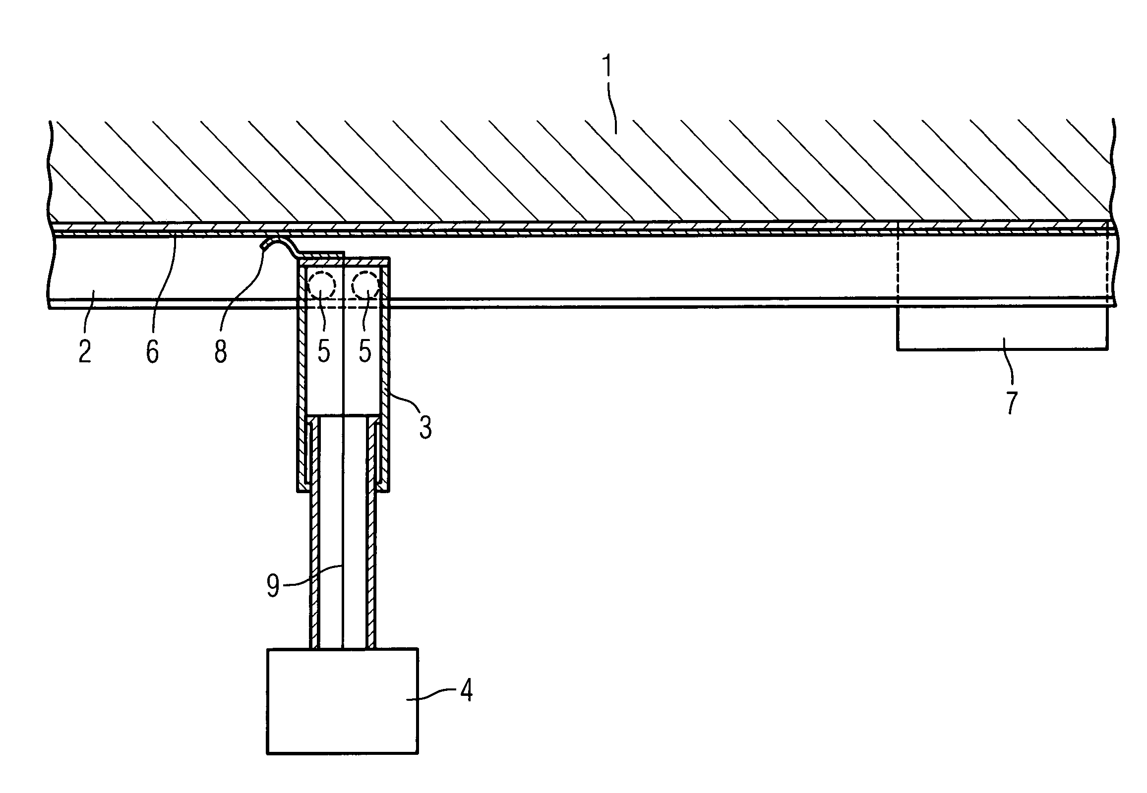
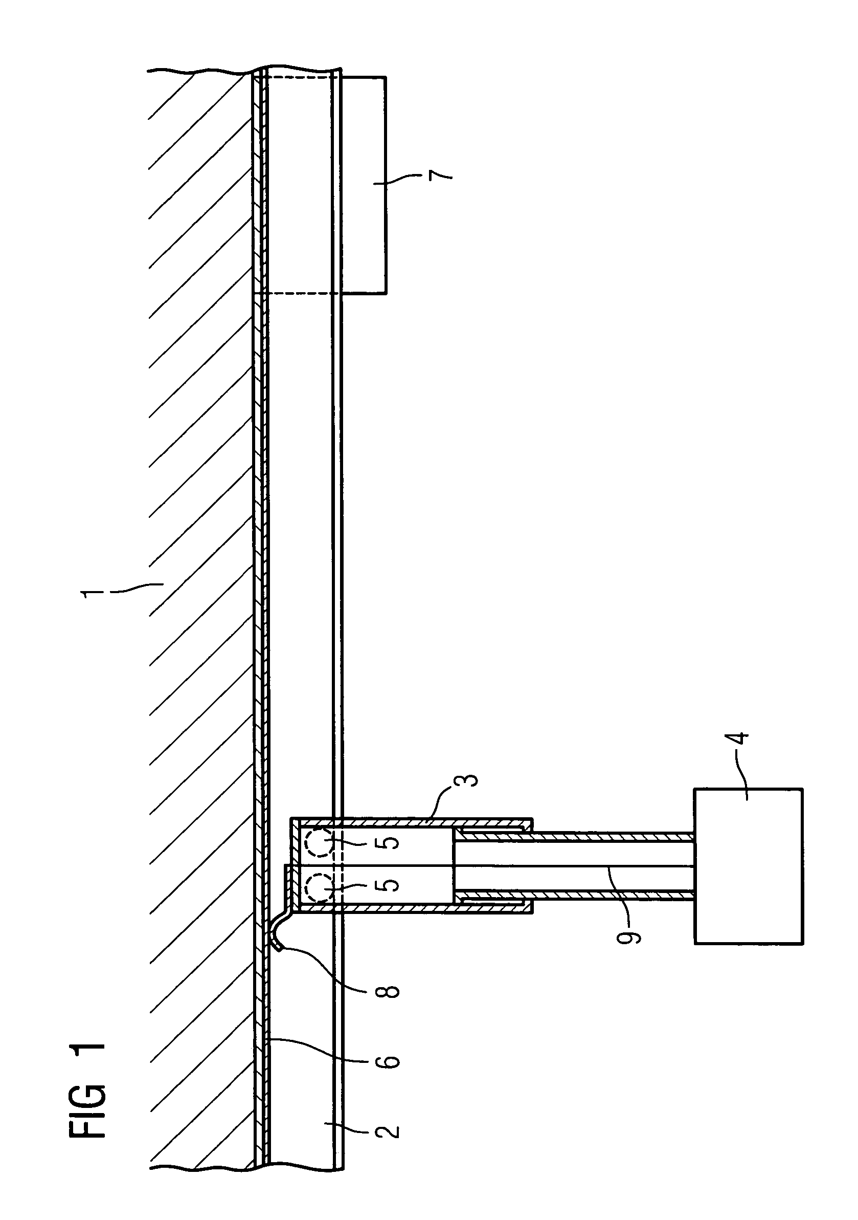
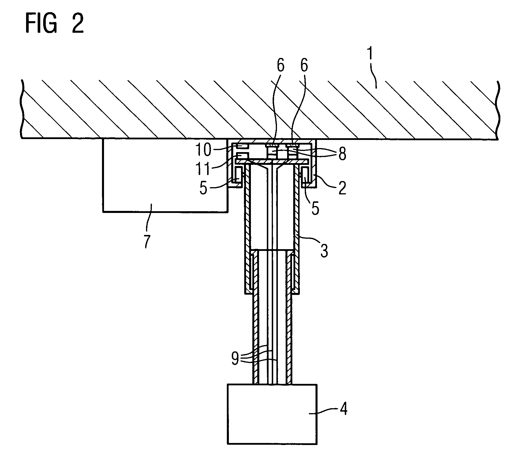
[0019]With the x-ray device shown in FIGS. 1 and 2, a guide rail 2 is fixed to a ceiling 1, along which guide rail a ceiling stand 3 can be moved which is preferably designed to be telescopable. An x-ray source 4, shown here schematically, is fixed to the end of the ceiling stand 3. The guide rail 2 can be designed according to a type of U-profile, with further U-profiles pointing inwards being fixed in turn to the two sides of the U-profile, said further U-profiles serving as tracks for rollers 5 fixed to the ceiling stand 2. Two conductor rails 6, which are connected to a generator 7 in an electrically conductive manner, are fixed to a base plate of the U-profile between the sides of the guide rail 3, preferably interconnecting with an electrically insulating layer (not shown here). Sliding contacts 8 are provided on the ceiling stand 3 corresponding to the conductor rails 6, said sliding contacts 8 being pushed against the conductor rails 6 using a spring-biased force. The slidin...


PUM


Abstract

The invention relates to an x-ray device with an x-ray source fixed to a ceiling stand and a generator connected therewith in order to supply it with power. For simplification purposes, it is proposed in accordance with the invention to provide a conductor rail between the generator and the x-ray source on the ceiling in order to produce an electrical connection, along which conductor rail a ceiling stand accommodating the x-ray source can be moved.

Description

CROSS REFERENCE TO RELATED APPLICATIONS[0001]This application claims priority to the German Application No. 10 2005 022 343.5, filed May 13, 2005 which is incorporated by reference herein in its entirety.FIELD OF INVENTION[0002]The invention relates to an x-ray device.BACKGROUND OF INVENTION[0003]Such an x-ray device is widely known according to the prior art. In such devices, a generator is positioned or mounted on the floor of a room accommodating the x-ray device. An x-ray source is fixed to a ceiling stand which is accommodated, for its part, in a moveable fashion in a guide rail mounted on the ceiling of the room. The x-ray source is connected to the generator via an at least 24 m long high-voltage cable. The high-voltage cable is fixed to the ceiling via a number of fixing means guided on the guide rail in a moveable manner and is suspended between the fixing means in loops. If the position of the x-ray source changes, the high-voltage cable can thus be moved to and fro thereb...

Claims


Application Information

Patent Timeline
Patent Type & Authority Patents(United States)
IPC IPC(8): H05G1/10H05G1/02
CPCA61B6/4464A61B6/56
Inventor MOLZ, CLAUDIUSSCHEUERING, PETER
Owner SIEMENS HEALTHCARE GMBH
Why Eureka
Try Eureka