
Vascular adjustable multi-gauge tilt-out method and apparatus for guiding needles

a multi-gauge, tilt-out technology, applied in tomography, catheters, applications, etc., can solve the problems of less support in the desired direction, limited needle guide size, and inability to fit between fixed parallel plates, so as to improve the efficiency of guiding needles, reduce the burden on physicians, and improve the effect of guiding needles

Inactive Publication Date: 2008-11-18
ASPEN SURGICAL PRODUCTS INC
View PDF53 Cites 104 Cited by
  • Summary
  • Abstract
  • Description
  • Claims
  • Application Information

AI Technical Summary

Benefits of technology

[0017]The present invention is an apparatus and method for guiding needles designed to satisfy the aforementioned needs, provide the previously stated objects, include the above-listed features, and achieve the already articulated advantages. The present invention is carried out in a “physician burden-less” manner in a sense that the burden on a physician or other medical professional in guiding needles during the process of tilting has been greatly reduced.
[0018]The present invention is also carried out in an inexpensive and durable way by avoiding the need to utilize a sliding mechanism and a spring.
[0019]Accordingly, the present invention is an apparatus and method including in one embodiment a slidable needle stop in a multi-gauge adjustable needle guide and in another embodiment, a pivoting needle stop.

Problems solved by technology

While these needle guides have been used extensively in the past, they do have some drawbacks.
First of all, any model of fixed parallel plate needle guide is limited in the size of needle that can be guided therein.
If the needle is too big, it will not fit between the fixed parallel plates.
If the plates are too far apart, there is less support being provided in the desired direction.
Also, these parallel plate needle guides only provide support in one direction.
This increases the attention required by the medical professional.
Secondly, the resilient slit tube type of needle guide does provide some resistance to motion in the desired plane of motion, but it is limited to only the first portion of that movement or motion.
They will not work well when a narrow gauge needle is used in a needle guide primarily designed for a larger needle.
Conversely, a larger needle may not fit in the tube, or it may be difficult to pull through the slit.
Additionally, these slit tube type of needle guides may be viewed as unstable in the direction of relative motion.

Method used


Image

  • Vascular adjustable multi-gauge tilt-out method and apparatus for guiding needles
  • Vascular adjustable multi-gauge tilt-out method and apparatus for guiding needles
  • Vascular adjustable multi-gauge tilt-out method and apparatus for guiding needles

Examples


Embodiment Construction

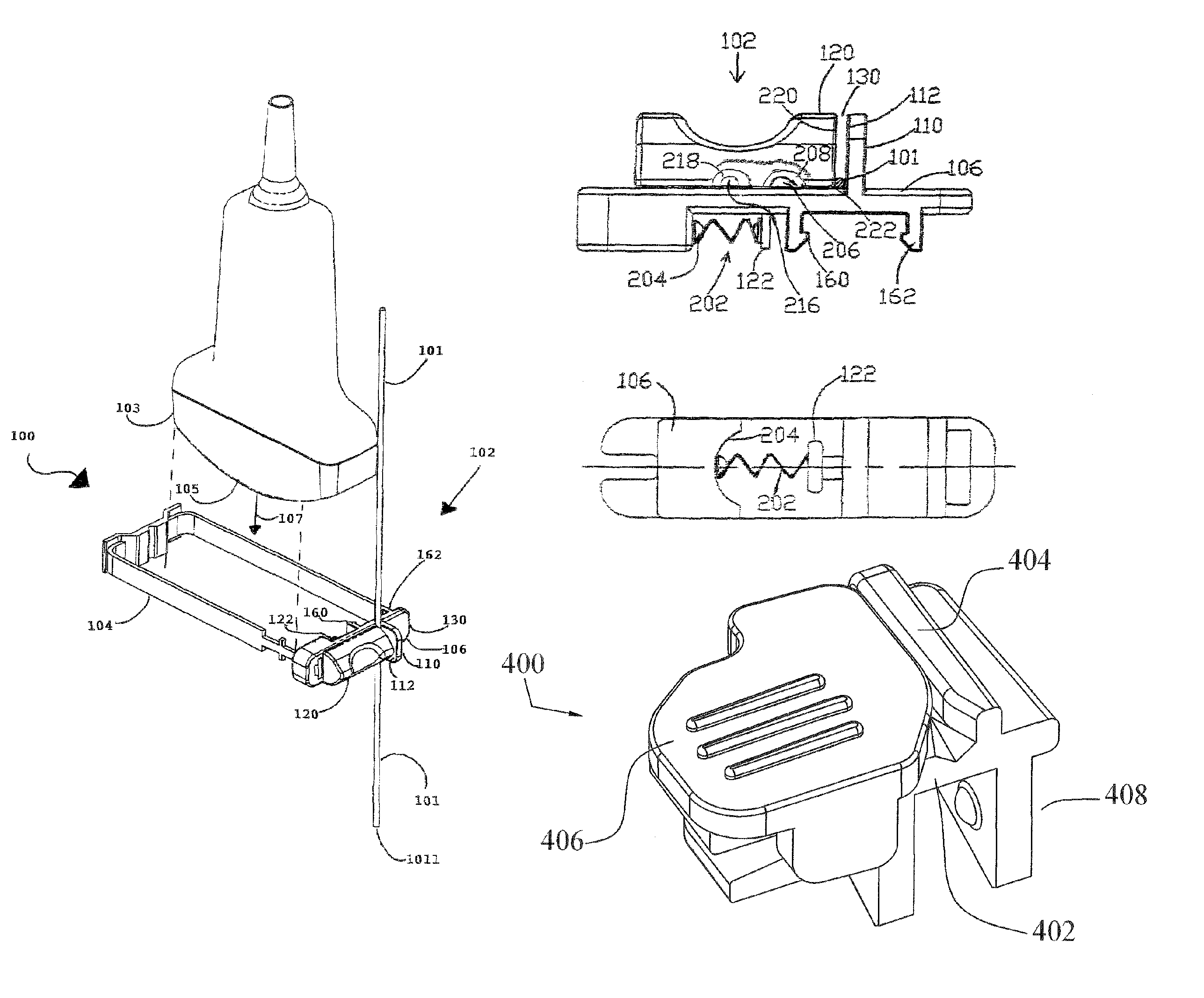
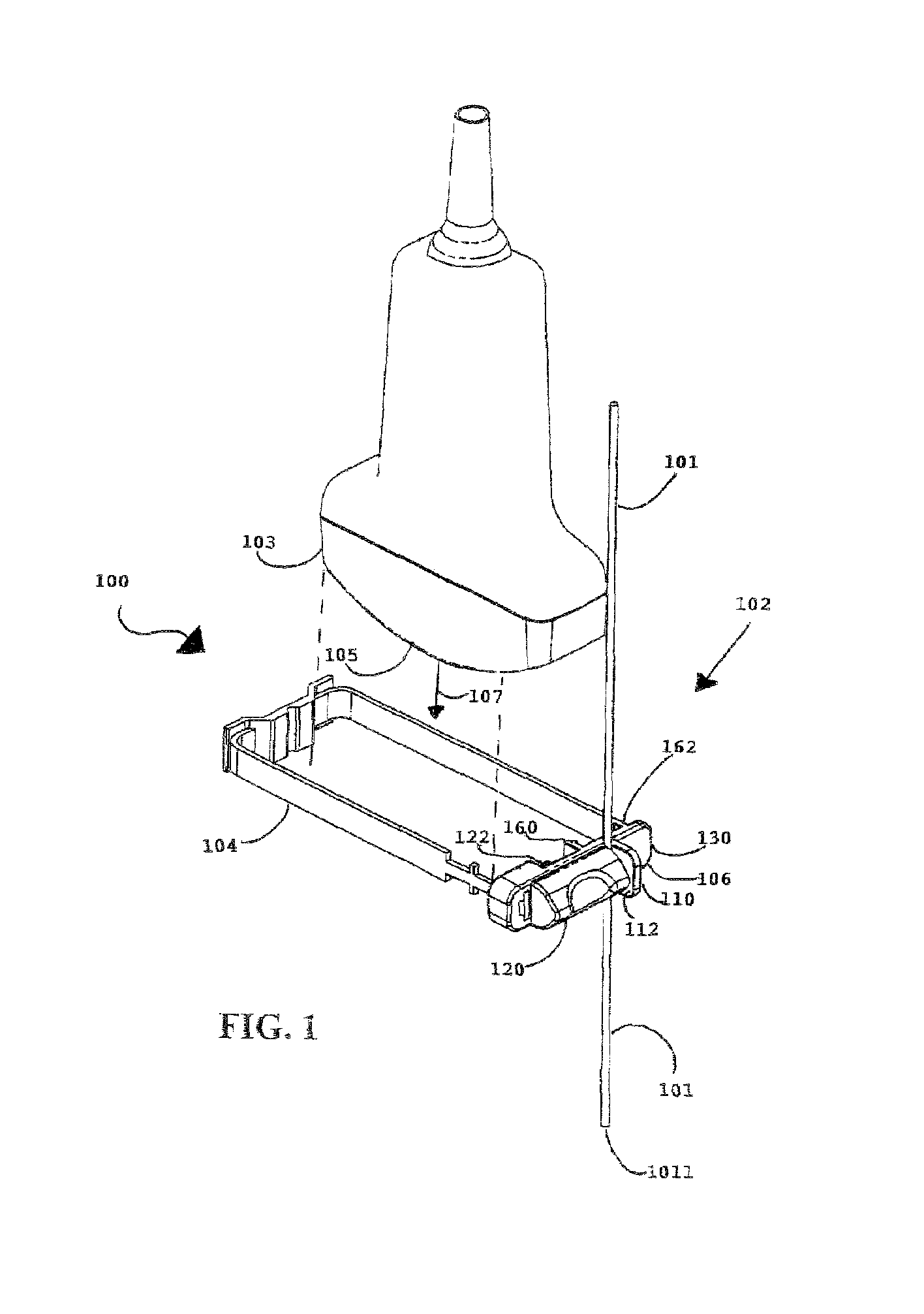
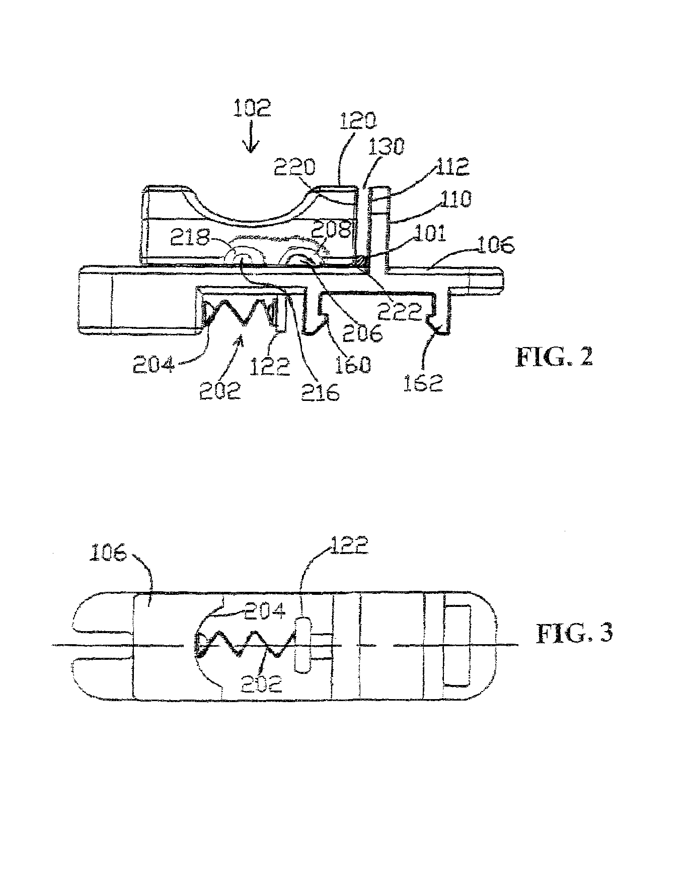
[0032]Now referring to the drawings wherein like numerals refer to like matter throughout, and more specifically referring to FIG. 1, there is shown a needle guide assembly 100 of the present invention which includes a needle guide 102 with a needle 101 disposed therein. Needle guide 102 is coupled to medical imaging device 103, which could be an ultrasound transducer, gamma ray transceiver or other imaging device, via a medical imaging device retaining strap 104, which could be an elastic strap, such as rubber or a less elastic strap, such as fabric or leather. Cables, wires, rope, brackets, clamps or any other suitable substitute could be used for a medical imaging device retaining strap 104. Needle guide 102 is preferably a plastic material, such as ABS or equivalent; however, other materials, such as aluminum, surgical steel, and any other suitable material could be substituted.

[0033]The medical imaging device 103 has a transmitting end 105, which may be a planar face with a ver...


PUM


Abstract

An apparatus and method for guiding a needle in conjunction with a biopsy using a medical imaging device, where an open-ended needle guide with an adjustable pivoting multi-gauge needle stop is used to guide a needle during insertion and during a tilting of the needle with respect to the medical imaging device.

Description

CROSS-REFERENCE TO RELATED APPLICATIONS[0001]The present invention is a continuation-in-part application of co-pending application entitled “Method and Apparatus for Guiding Needles” by the same inventor, the application having Ser. No. 10 / 250,149 filed on Jun. 6, 2003, which is a continuation of application Ser. No. 09 / 682,367 entitled “Method and apparatus for guiding needles”, filed by the same inventor on Aug. 24, 2001, which application has now issued as U.S. Pat. No. 6,612,990, and which itself was based upon a continuation-in-part application of an application entitled “Needle guide for attachment to ultrasound transducer probe” by the same inventor, the application having Ser. No. 09 / 526,048, which was filed on Mar. 15, 2000, and issued as U.S. Pat. No. 6,296,614 on Oct. 2, 2001, which itself was a continuation-in-part of application 29 / 103,098, also entitled “Needle guide for attachment to ultrasound transducer probe” filed on Apr. 8, 1999, which issued as U.S. Pat. No. Des...

Claims


Application Information

Patent Timeline
IPC IPC(8): A61B8/00
CPCA61B8/0833A61B8/0841A61B17/3403A61B10/02A61B2017/3405A61B2017/3413
Inventor PRUTER, RICK L
Owner ASPEN SURGICAL PRODUCTS INC
Learn More