Portable wireless device

a wireless device and portable technology, applied in the direction of polarisation/directional diversity, resonant antennas, substantially flat resonant elements, etc., can solve the problems of user time and communication cost, difficult to realize high speed transmission in downlink communication, etc., to improve reception performance, improve antenna directivity, and high antenna radiation efficiency

Inactive Publication Date: 2008-11-18
PANASONIC CORP
View PDF15 Cites 85 Cited by
  • Summary
  • Abstract
  • Description
  • Claims
  • Application Information

AI Technical Summary

Benefits of technology

[0013]According to the present invention, for example, when an antenna of a mobile radio apparatus is formed with three antenna elements, if the second antenna element or the third antenna element is selected in conjunction with the voice communication state, it is possible in the transmission system to optimally control the antenna directivity by providing a predetermined phase difference between the selected antenna element (for example, the second antenna element) and the first antenna element and feeding the antenna elements. By this means, it is possible to ensure high antenna radiation efficiency with respect to the radio waves in the required direction. Further, in the reception system, it is possible to improve the reception performance and perform high speed transmission in downlink communication by performing combining reception diversity in accordance with the reception state of the second antenna element or the third antenna element.
[0014]In addition, according to the present invention, a combining section (that is, a demodulator) performs adaptive combining of signals by assigning a desired weight in accordance with the reception states of received signals from the first antenna element, the second antenna element, and the third antenna element. By this means, it is possible to maintain reception performance in an excellent state, and therefore, it is possible to realize high speed transmission in downlink communication.
[0015]Further, according to the present invention, a selection switching section selects the second antenna element or the third antenna element in conjunction with the voice communication state, thereby the selected antenna element (for example, the second antenna element) and the first antenna element excite with a predetermined phase difference, so that it is possible to ensure high antenna radiation efficiency by increasing the antenna directivity in a desired direction in the transmission system. At this time, in the reception system, it is possible to perform high speed transmission in downlink communication by increasing reception performance by reception combining of two antenna elements (for example, the second antenna element and the first antenna element).
[0016]Furthermore, according to the present invention, an inclination detection section detects the use state from the inclination angle of the mobile radio apparatus, so that it is possible in the transmission system to perform directivity control in the required direction of radio waves in various use states (that is, a voice communication state where voice communication is being carried out or an operation state where email operations are being performed). Accordingly, it is possible to ensure excellent communication performance even in any use state. For example, in the voice communication state in which a mobile radio apparatus (mobile phone) is held in the right hand and voice communication is carried out, or in the operation state in which a mobile radio apparatus is held in the left hand and email operations are performed, the inclination detection section detects the inclinations of the mobile radio apparatus in the use states, thereby ensuring the maximum radio wave directivity and maintaining excellent communication performance.
[0017]Still furthermore, according to the present invention, when a foldable mobile phone is used, the directivity of a radio wave is controlled by automatically changing the feeding phase of two or more antenna elements in accordance with the use state or the reception state of the foldable mobile phone, so that it is possible to perform the optimum directivity control with respect to a direction of a required radio wave. By this means, it is possible to maintain the optimum transmission performance in accordance with the use state of the foldable mobile phone, and therefore it is possible to further improve the transmission performance, compared to the conventional foldable mobile phone. On the other hand, when reception is performed, high speed transmission in downlink communication can be ensured by the reception combining scheme. Accordingly, by means of the present invention, it is possible to configure a foldable mobile phone of high communication quality.

Problems solved by technology

In the communication system of the CDMA (Code Division Multiple Access) scheme now in service widely, the maximum transmission rate of downlink communication is 384 kbps and, with such a communication rate, a considerable time and communication cost are required if the user downloads a large volume of moving images etc.
With such an antenna switching diversity scheme, however, it is difficult to realize a high speed transmission in downlink communication.

Method used


Image

  • Portable wireless device
  • Portable wireless device
  • Portable wireless device

Examples


embodiment 1

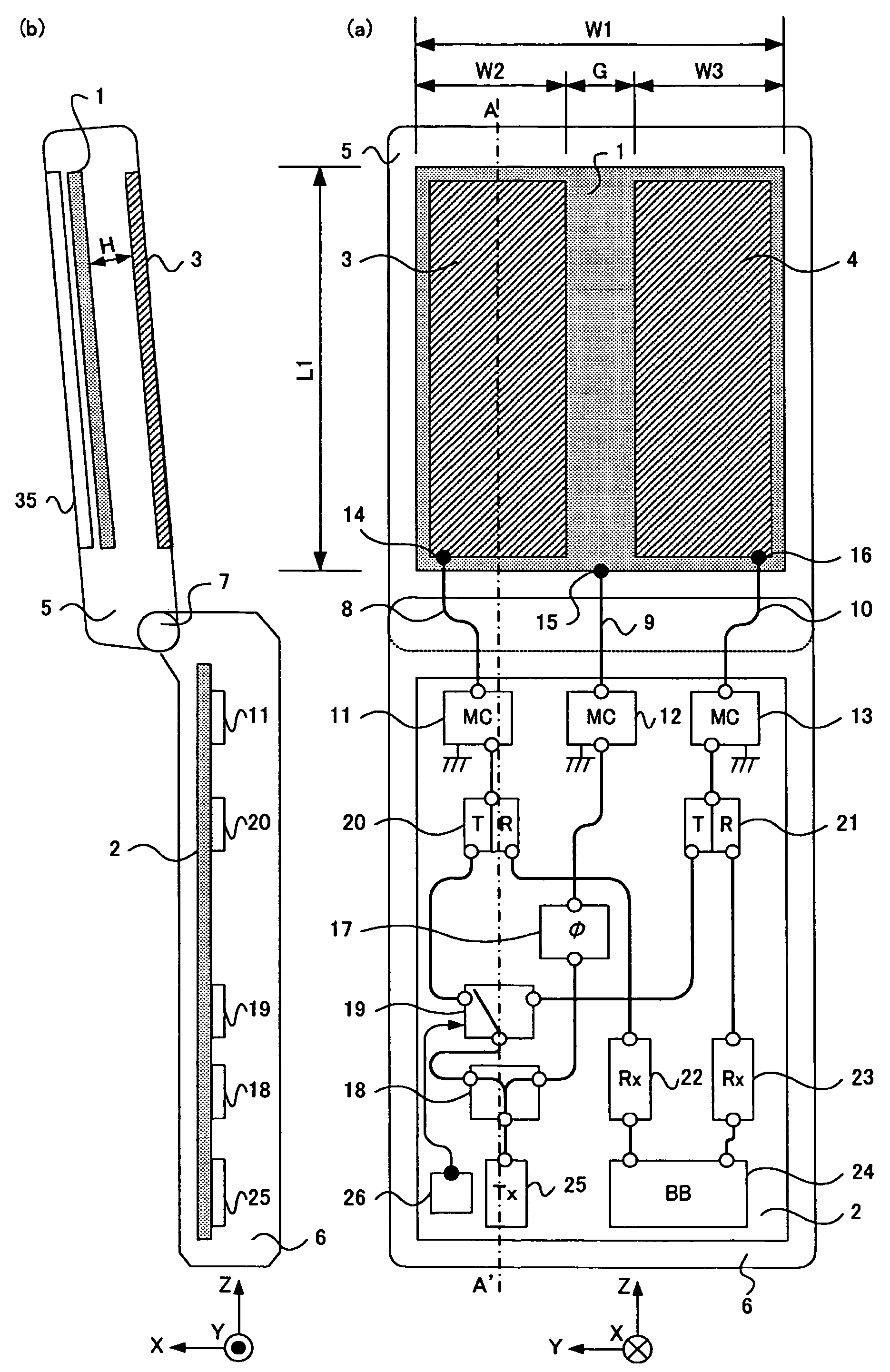
[0031]FIG. 1 is a configuration diagram of a foldable mobile phone of Embodiment 1 of the present invention, and FIG. 1(a) is a back perspective view of the foldable mobile phone when viewed from the backside and FIG. 1(b) is an A-A′ section view in FIG. 1(a). In other words, FIG. 1 shows a front view and a side view of a state in which the mobile phone having a foldable structure is opened to use (hereinafter, referred to an “open state”). The foldable mobile phone has a configuration including upper case 5, lower case 6, hinge section 7, flat conductor 1 (first antenna element), flat conductor 3 (second antenna element), flat conductor 4 (third antenna element), ground plate 2, and display section 35. In the description below, the foldable mobile phone may be simply referred to as a “mobile phone” in some cases.

[0032]Upper case 5 corresponding to the upper housing and lower case 6 corresponding to the lower housing are made of resin that is an insulator, and, in general, upper cas...

embodiment 2

[0053]FIG. 6 is a configuration diagram of a foldable mobile phone in embodiment 2 of the present invention; FIG. 6(a) is a back perspective view when the foldable mobile phone is viewed from the backside; and FIG. 6(b) is a B-B′ section view in FIG. 6(a). The mobile phone shown in FIG. 6 is obtained by adding a duplexer 30 to the system of flat conductor 1 and by further adding a reception circuit (reception section) 31 to the reception system of this duplexer 30, compared to the mobile phone shown in FIG. 1. Other components are the same as in FIG. 1 and are assigned the same codes. Therefore, the duplicated explanation will be omitted.

[0054]In FIG. 6, a high frequency signal is distributed from transmission circuit 25 by power distributor 18, and one of the distributed signals is fed to flat conductor 1 from matching circuit 12 via phase shifter 17 and duplexer 30. The other is fed to flat conductor 3 from one contact of high frequency switch 19 via duplexer 20 and matching circu...

embodiment 3

[0059]FIG. 7 is a configuration diagram of a foldable mobile phone of Embodiment 3 of the present invention; FIG. 7(a) is a back perspective view when the foldable mobile phone is viewed from the backside; and FIG. 7(b) is a C-C′ section view in FIG. 7(a). The mobile phone shown in FIG. 7 is obtained by deleting high frequency switch 19, power distributor 18, and phase shifter 17 from the mobile phone shown in FIG. 6 and newly adding power distributor 40 for distributing a signal to three systems, phase shifter 41, and phase shifter 42. Other components are the same as in FIG. 6 and are assigned the same codes. Therefore, the duplicated explanation of the mobile phone shown in FIG. 1 and FIG. 6 will be omitted.

[0060]In FIG. 7, in the case of the transmission system, a high frequency signal is distributed to three systems from transmission circuit 25 by power distributor 40 and the first system is fed to flat conductor 3 from matching circuit 11 via phase shifter 41 and duplexer 20. ...


PUM


Abstract

A portable wireless device realizing high-speed transmission in downlink communication in a used state that a foldable portable wireless device is held in a hand of the user and ensuring a high antenna radiation efficiency. In the portable wireless device, platy conductors (1, 3, 4) are arranged in the longitudinal direction on the back of a display section (35) of an upper case (5). The signal of a transmission circuit (25) is distributed by a power distributor (18). One signal is fed to a platy conductor (1) through a phase shifter (17) and the other is fed to the platy conductor (3) or the platy conductor (4) from a high-frequency switch (19) through a transmission / reception duplexer (20) or a transmission / reception duplexer (21). The high-frequency switch (19) selectively feeds power to either the platy conductor (3) or the platy conductor (4) according to the signal from a gravity sensor (26). The received signal is extracted by the transmission / reception duplexers (20, 21), amplified by a receiving circuit (22) and a receiving circuit (23), and multiplied by a predetermined weight coefficient by a demodulating section (24) and combined.

Description

TECHNICAL FIELD[0001]The present invention relates to a mobile radio apparatus having a foldable structure.BACKGROUND ART[0002]The foldable mobile phone widely used recently is used in many cases for email or as a TV telephone, and further, is used to download a variety of information, such as music and video images, by using the Internet as well as being used as a voice phone to carry out voice communication. In particular, when a user downloads a large volume of images, it is important to increase the transmission rate of the downlink communication of the mobile phone (that is, the communication from the telephone station to the user terminal). In the communication system of the CDMA (Code Division Multiple Access) scheme now in service widely, the maximum transmission rate of downlink communication is 384 kbps and, with such a communication rate, a considerable time and communication cost are required if the user downloads a large volume of moving images etc.[0003]Now, in the HSD...

Claims


Application Information

Patent Timeline
Patent Type & Authority Patents(United States)
IPC IPC(8): H01Q1/24H01Q1/38H01Q21/00H01Q3/24H01Q3/26H01Q5/00H01Q9/04H01Q9/40H04B1/38H04B7/06H04B7/08H04B7/10H04B7/26H04M1/02H04W16/28H04W88/02
CPCH01Q1/242H01Q1/243H01Q3/24H01Q9/0407H01Q9/40H04B7/0602H04B7/0802
Inventor NISHIKIDO, TOMOAKISAITO, YUTAKAKOYANAGI, YOSHIOEGAWA, KIYOSHI
Owner PANASONIC CORP
Why Eureka
Try Eureka