
Method and apparatus for dynamic data flow control using prioritization of data requests

Inactive Publication Date: 2008-11-18
PARALLEL NETWORKS
View PDF28 Cites 508 Cited by
  • Summary
  • Abstract
  • Description
  • Claims
  • Application Information

AI Technical Summary

Benefits of technology

[0006]From the foregoing, it may be appreciated that a need has arisen for a method and apparatus for dynamic data flow control so as to provide increased efficiency for handling large numbers of requests by a web site.
[0009]The present invention provides a number of technical advantages. One such technical advantage is the capability to prioritize requests based on a request and an origin server to which the request is addressed for controlling the processing load at the origin server. Another such technical advantage is the capability to configure a data center for independent control of the processing load experienced by different origin servers. A further technical advantage is the capability to provide status information about the request to a user associated with the request based on the delay in processing the request and other configurable criteria associated with the origin server.

Problems solved by technology

In addition, as increasing numbers of requests are handled by the Internet, the delay experienced by the user between generating the request and receiving a response is also increasing.
However, traditional solutions have often failed as the number of requests continue to increase because of the expense associated with maintaining large numbers of web servers and high speed connections to the Internet.
Traditional electronic commerce systems have often failed similar levels of provide faster and more personalized service to different electronic commerce customers.

Method used


Image

  • Method and apparatus for dynamic data flow control using prioritization of data requests
  • Method and apparatus for dynamic data flow control using prioritization of data requests
  • Method and apparatus for dynamic data flow control using prioritization of data requests

Examples


Embodiment Construction

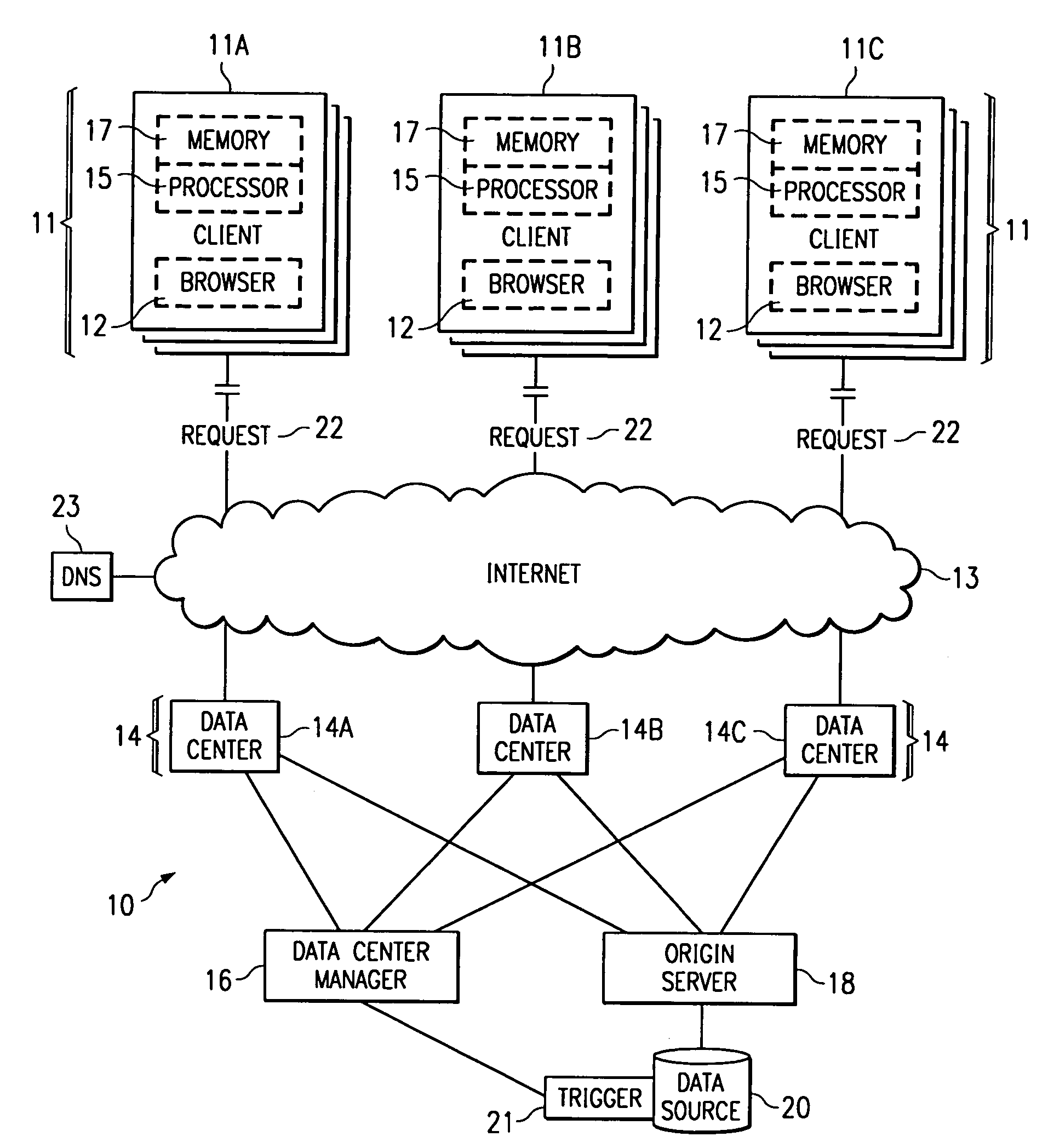
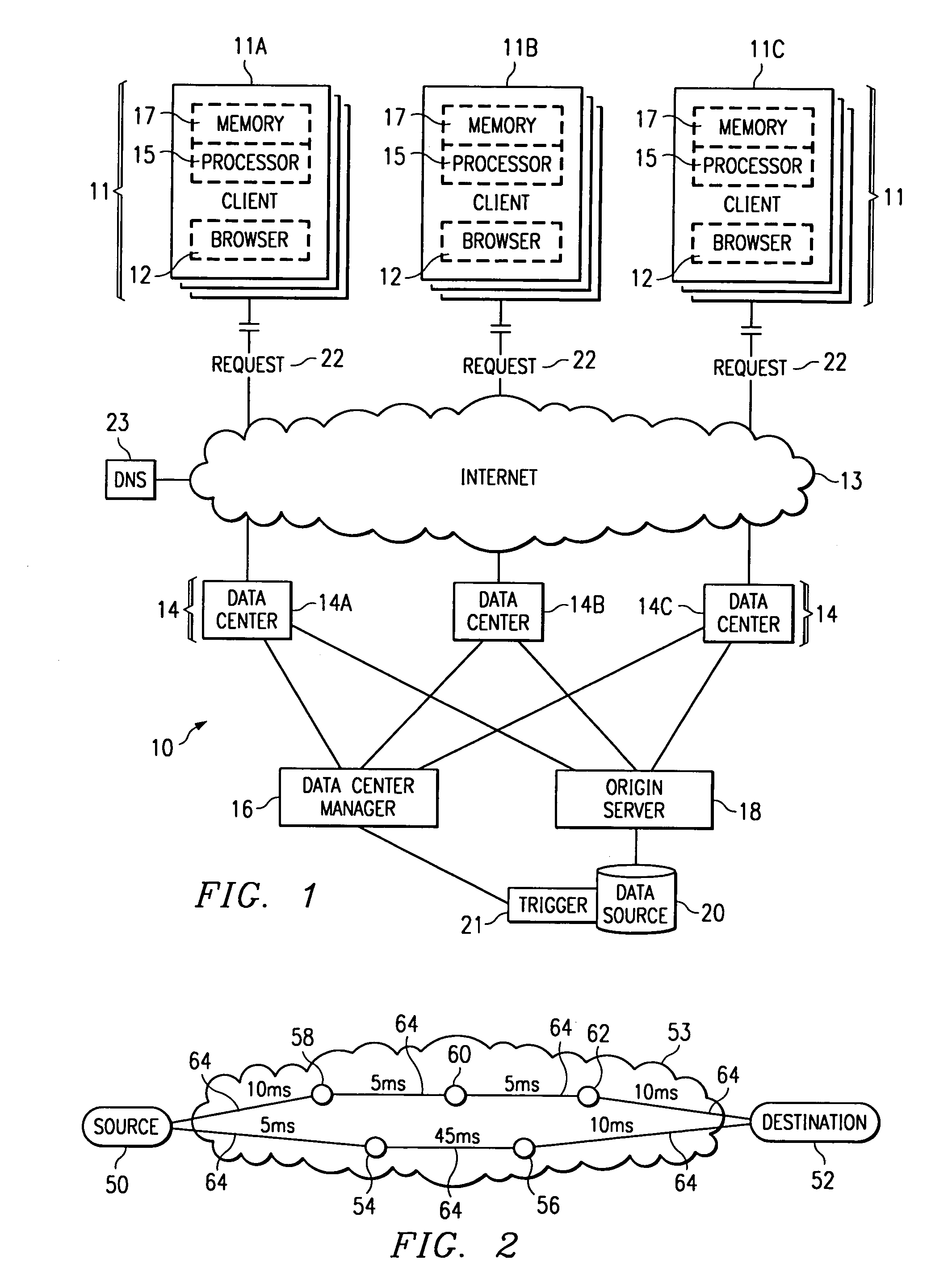
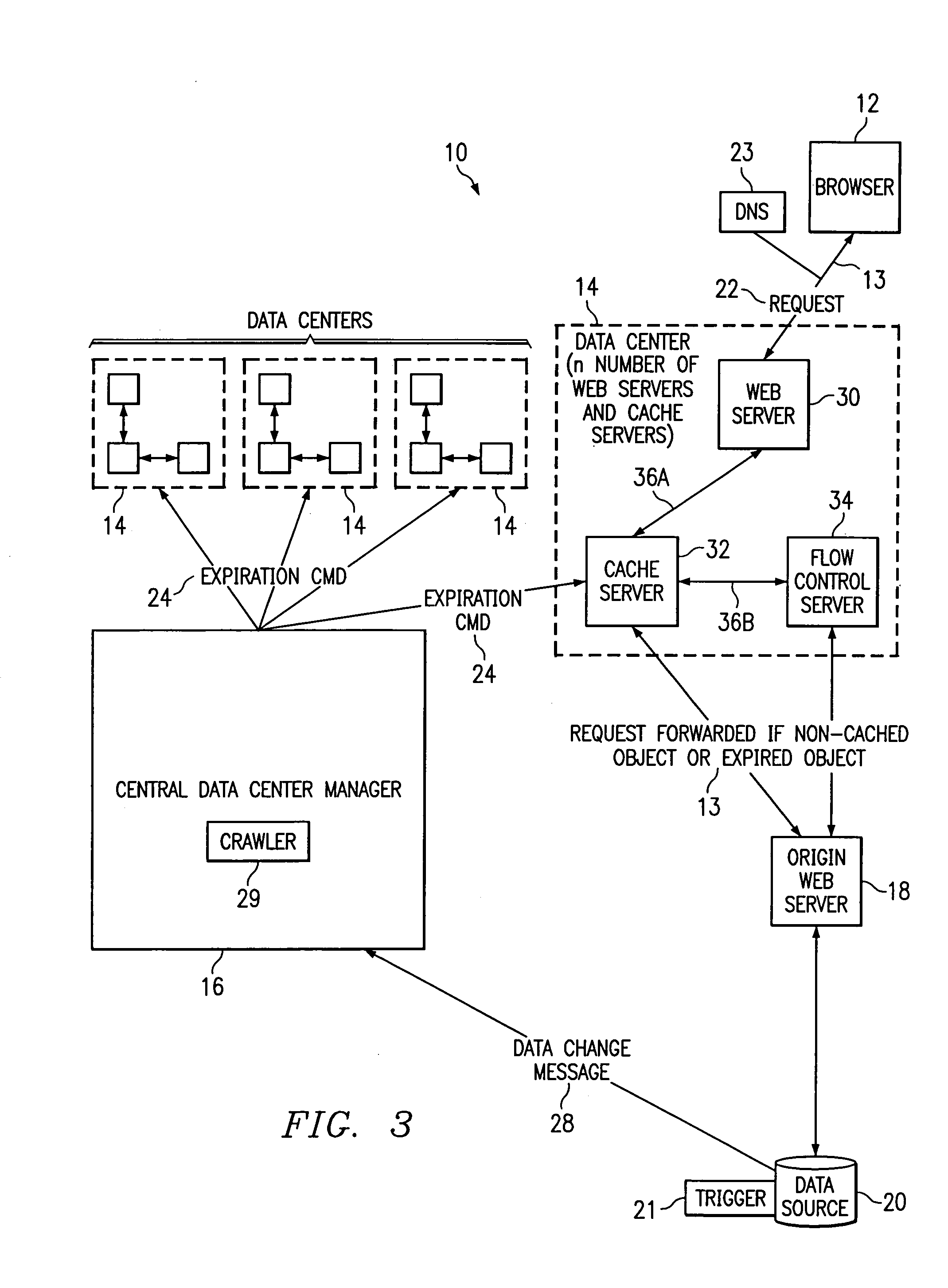
[0017]FIG. 1 is a block diagram of a web content caching system 10. Caching system 10 comprises a plurality of clients 11, a browser 12 executing on client 11, a network 13, one or more data centers 14, a data center manager 16, an origin server 18, a data source 20 and a Domain Name Service (DNS) server 23. Caching system 10 provides increased World Wide Web (“web”) performance to clients 11. Performance is increased by caching data at the data centers 14 so that the data is located closer, in terms of network distance, to the clients 11, by decreasing the volume of data requests handled by origin server 18 and by decreasing the volume of dynamic data to be generated by origin server 18. It should be understood that while the disclosed embodiment is discussed in terms of the Internet Protocol (IP), any suitable network protocol could be used, such as Asynchronous Transfer Mode (ATM), frame relay and Fiber Distributed Data Interface (FDDI).

[0018]Each client 11 comprises any suitable...


PUM


Abstract

A data center (14) receives a request (22) for content from a browser (12) on a client (11). The data center determines whether the requested content is available at the data center. The content is available when the content is both present at the data center and current. The content may be expired and marked as non-available in response to an expiration command (24). When the requested content is available at the data center, the data center returns the requested content to the data center. When the requested content is locally unavailable at the data center, the requested content is retrieved from an origin server (18). The retrieval of the content from the origin server may be delayed based on the processing load at the origin server. When retrieval of the content is delayed, the request is prioritized and placed in a queue for handling by the origin server based on the priority of the request. Also, when retrieval of the content is delayed, a status page may be communicated to the browser to inform a user of the delay and provide alternate content (139) and status information related to the request determined as a function of the request or the current state of the origin server.

Description

RELATED APPLICATIONS[0001]This application claims the benefit of U.S. Provisional Application Ser. No. 60 / 180,587, filed Feb. 7, 2000 by Keith A. Lowery, et al., and entitled, “Method and Apparatus for Dynamic Data Flow Control”.TECHNICAL FIELD OF THE INVENTION[0002]This invention relates in general to client-server systems and, more particularly, to a method and apparatus for dynamic data flow control.BACKGROUND OF THE INVENTION[0003]As computers have grown increasingly important in today's society, the importance of the Internet has also increased. As increased numbers of users access the Internet, the need for a web server to handle large numbers of data requests has also increased. In addition, as increasing numbers of requests are handled by the Internet, the delay experienced by the user between generating the request and receiving a response is also increasing.[0004]Some traditional solutions to handling large numbers of data requests and decreasing the delay at the web serve...

Claims


Application Information

Patent Timeline
IPC IPC(8): G06F15/16
CPCH04L47/10H04L63/101H04L67/1008H04L67/2842H04L67/1002H04L67/28H04L43/0817H04L43/0852H04L43/16H04L63/10H04L67/1001H04L67/56H04L67/568
Inventor LOWERY, KEITH A.DAVIDSON, DAVID K.SAXENA, AVINASH C.
Owner PARALLEL NETWORKS
Learn More