Waste heat recovery system of heat source, with Rankine cycle

a heat recovery system and heat source technology, applied in steam engine plants, machines/engines, combustion engines, etc., can solve the problems of excessive cooling water flow through the cooling water circuit, ineffective operation of the engine, and insufficient cooling water flow, so as to reduce the cooling performance, effectively use the waste heat of the thermal medium, and stable secure

Inactive Publication Date: 2008-11-25
DENSO CORP
View PDF17 Cites 36 Cited by
  • Summary
  • Abstract
  • Description
  • Claims
  • Application Information

AI Technical Summary

Benefits of technology

[0009]In view of the foregoing problems, it is an object of the present invention to effectively use waste heat of the thermal medium heated by a heat source (heat generating element, e.g., engine) without reducing a cooling performance of the heat source, which is cooled by circulation of the thermal medium. It is another object of the present invention to produce a waste heat recovery system of the heat source, in which a heat amount can be stably secured on the side of the Rankine cycle without reducing the cooling performance of the heat source.
[0011]Because the heater is arranged in parallel with the cooling heat exchanger with respect to the flow of thermal medium, a flow resistance of the thermal medium flowing through the cooling heat exchanger is not increased due to the arrangement of the heater of the Rankine cycle. Thus, waste heat energy of the thermal medium can be effectively used without affecting the cooling performance of the heat source such as the engine. For example, the thermal medium is cooling water.

Problems solved by technology

In addition, when a heat consumption in the Rankine cycle becomes excessively large, the flow amount of cooling water flowing through the cooling water circuit 20′ excessively decreases, and an engine operation (e.g., fuel vaporization in the engine 10) is not effectively performed.
Therefore, when the refrigerant cycle is operated in summer or the like, the compressor cannot be used as the expansion device in the Rankine cycle.
In this case, a power recovery operation cannot be performed in the Rankine cycle.

Method used


Image

  • Waste heat recovery system of heat source, with Rankine cycle
  • Waste heat recovery system of heat source, with Rankine cycle
  • Waste heat recovery system of heat source, with Rankine cycle

Examples


first embodiment

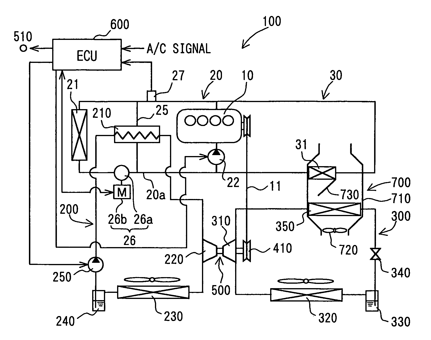
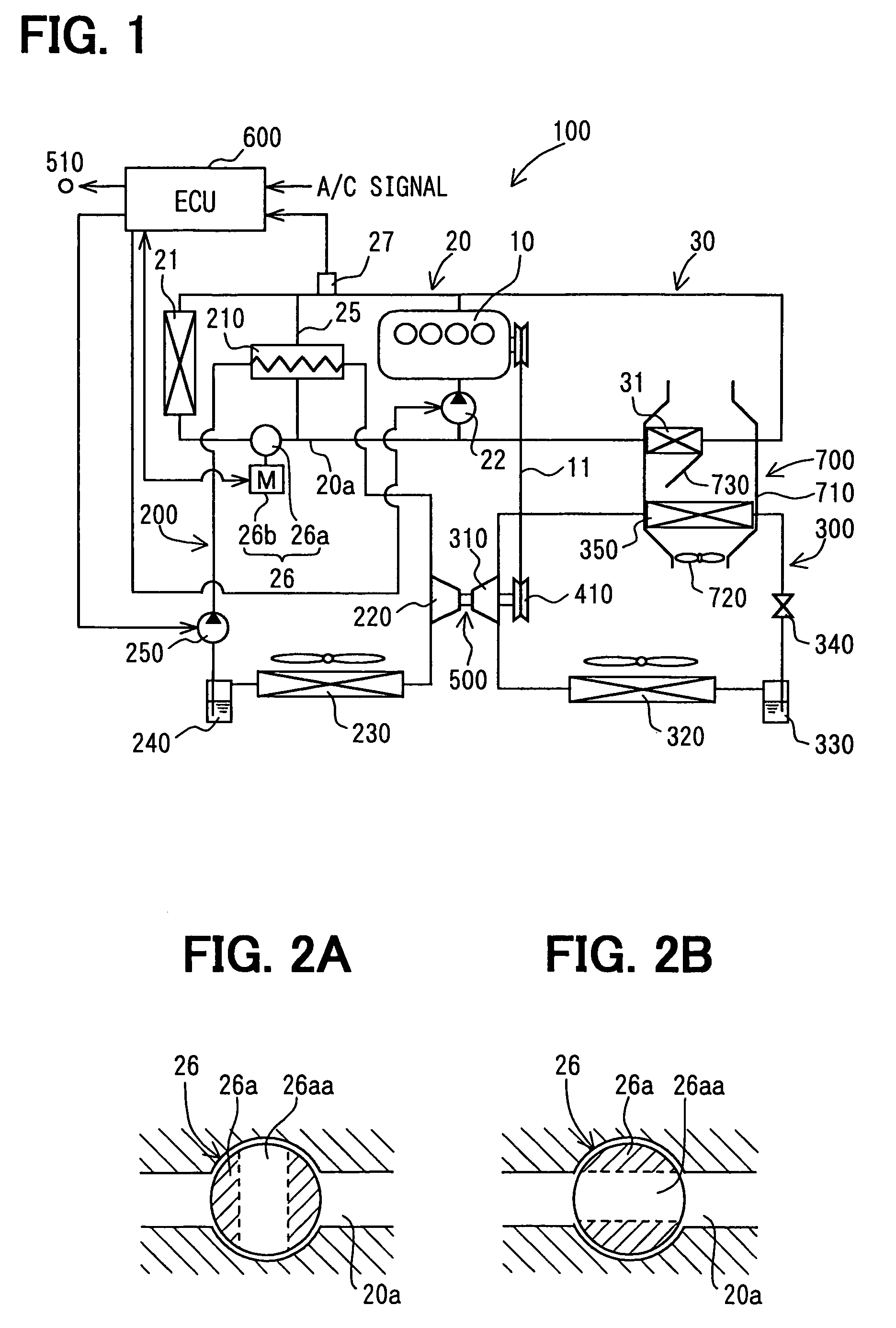
[0039]The first embodiment of the present invention will be now described with reference to FIGS. 1-4. As shown in FIG. 1, a waste heat recovery system 100 for recovering waste heat of an internal combustion engine 10 is constructed with a Rankine cycle 200 and a refrigerant cycle 300.

[0040]The internal combustion engine 10 is a water-cooled engine cooled by circulation of cooling water. The engine 10 includes a circulation path (not shown) inside a cylinder block or the like. The circulation path is located around a combustion chamber (not shown) of the engine 10. Cooling water flows through the circulation path so as to perform a heat transmitting of heat energy from the engine 10 to the cooling water. The heat energy is a part of energy generated by combustion performed in the combustion chamber of the engine 10. The cooling water is heated in the engine 10, circulated in the circulation path of the engine 10, and then cooled in a cooling water circuit 20 including a radiator 21....

second embodiment

[0081]The second embodiment of the present invention will be now described with reference to FIGS. 5 and 6.

[0082]A switching valve 126, which has a generally known thermostat, is used in the second embodiment, instead of the electrically driven switching valve 26 described in the first embodiment.

[0083]As shown in FIG. 5, the control unit 600 controls the hot water pump 22, but does not control the switching valve 126, in accordance with the outlet water temperature Tw of the engine 10. The thermostat responds to the temperature of cooling water flowing through the cooling water circuit section 20a, so that the radiator distribution flow amount is controlled by the switching valve 126 from zero to the maximum flow amount.

[0084]The hot water pump 22 is an electrically driven pump. Therefore, a discharge amount (discharge capacity) of the electrically driven hot water pump 22 is not limited due to a rotation speed of the engine 10, compared with a mechanical type pump. The discharge a...

third embodiment

[0092]The third embodiment of the present invention will be now described with reference to FIGS. 7 and 8.

[0093]As shown in FIG. 7, a hot water pump 122, which has a generally known mechanical structure, is used in the third embodiment, instead of the electrically driven hot water pump 22 described in the first embodiment. Further, the control unit 600 controls the switching valve 26, but does not control the hot water pump 122.

[0094]The switching valve 26 is an electrically driven switching valve. Therefore, the control unit 600 can control the switching valve 26 without delaying, compared with a conventional switching valve using a thermostat which has a relatively slow response control characteristic. The radiator distribution flow amount is controlled at a predetermined flow amount in accordance with the outlet water temperature Tw detected by the water temperature sensor 27, for example.

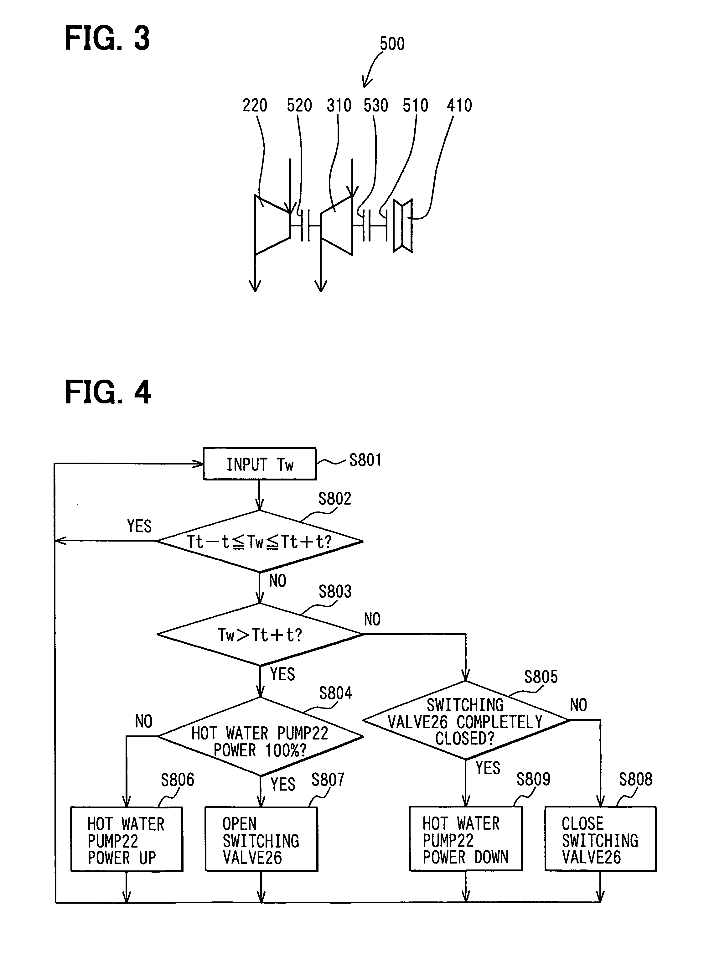
[0095]Next, the control operation (third control operation) for controlling the flow amount ...


PUM


Abstract

A waste heat recovery system of an engine has a cooling water circuit and a Rankine cycle. Cooling water is circulated between the engine and a radiator in the cooling water circuit. The Rankine cycle has a heater and an expansion device. The heater performs heat exchange between the cooling water heated by the engine and an operation fluid so as to heat the operation fluid in the Rankine cycle. The expansion device expands the heated operation fluid, so as to generate driving power. The heater is arranged in a bypass circuit so as to be in parallel with the radiator with respect to the cooling water flow. Thus, waste heat of the cooling water heated by the engine can be effectively recovered without reducing a cooling capacity of the radiator.

Description

CROSS REFERENCE TO RELATED APPLICATION[0001]This application is a CIP application of U.S. application Ser. No. 10 / 873,971, filed on Jun. 21, 2004. The present application is related to Japanese Patent Applications No. 2003-178599 filed on Jun. 23, 2003 and No. 2003-403492 filed on Dec. 2, 2003, the disclosure of which is incorporated herein by reference.FIELD OF THE INVENTION[0002]The present invention is related to a waste heat recovery system used for a heat generating element (heat source), such as a motor and a heat engine. More particularly, the present invention is suitable for a power recovery using waste heat of an internal combustion engine of a vehicle for example.BACKGROUND OF THE INVENTION[0003]According to JP-B2-2540738, a Rankine cycle is constructed using components of a refrigerant cycle in a vehicle internal combustion engine or the like. The Rankine cycle is constructed as a generally known waste heat recovery system of a heat generating element such as an internal...

Claims


Application Information

Patent Timeline
Patent Type & Authority Patents(United States)
IPC IPC(8): F01K23/10F01K23/06F02G5/00
CPCF01K23/065F02G5/00Y02T10/166Y02T10/12
Inventor HAMADA, SHINICHISASAKI, MINORUINABA, ATSUSHI
Owner DENSO CORP
Why Eureka
Try Eureka