Method for manufacturing heat pipe cooling device

a technology of cooling device and heat pipe, which is applied in the direction of electrical apparatus construction details, indirect heat exchangers, lighting and heating apparatus, etc., can solve the problems of reducing and achieve the effect of enhancing the efficiency of heat transfer

Inactive Publication Date: 2008-11-25
GOLDEN SUN NEWS TECHN
View PDF11 Cites 42 Cited by
  • Summary
  • Abstract
  • Description
  • Claims
  • Application Information

AI Technical Summary

Benefits of technology

[0008]Since the heat conductivity of the heat pipe is much larger than that of the copper heat conductor, directly contacting the heat pipe to the heat generating electronic device will enhance the efficiency of heat transfer. For this reason, a heat pipe cooling device, which includes a cooling end embedded in a heat conductor, is developed, so as to contact both the heat conductor and the heat pipe to a heat generating electronic device, as shown in FIG. 2. Therefore, one objective of the present invention is to provide a method for manufacturing a heat pipe cooling device that allows both the heat pipe and the heat conductor to contact the heat generating electronic device.
[0009]Another, the present invention is to provide a method for manufacturing a heat pipe cooling device, which does not requires a third media. Since the combination of the heat pipe and the heat conductor is normally achieved by a soldering processing, the low heat conductivity of the soldering material will form a thermal resistance on the interface, which will reduce the efficiency of heat transfer. It is more reasonable to combine the heat pipe and the heat conductor via direct connection, so as to eliminate the effect of thermal resistance.
[0010]In the present invention, an upper cover is used to press the heat pipe to the heat conductor. Therefore, the manufacturing process does not require a soldering process and an oxidation reduction process, which will largely enhance the production yield and reduce the production cost. Therefore, yet another objective of the present invention is to provide a quick and cost effective method for manufacturing the heat pipe cooling device.

Problems solved by technology

Since the combination of the heat pipe and the heat conductor is normally achieved by a soldering processing, the low heat conductivity of the soldering material will form a thermal resistance on the interface, which will reduce the efficiency of heat transfer.

Method used


Image

  • Method for manufacturing heat pipe cooling device
  • Method for manufacturing heat pipe cooling device
  • Method for manufacturing heat pipe cooling device

Examples


Embodiment Construction

[0021]In order to better understanding the features and technical contents of the present invention, the present invention is hereinafter described in detail by incorporating with the accompanying drawings. However, the accompanying drawings are only for the convenience of illustration and description, no limitation is intended thereto.

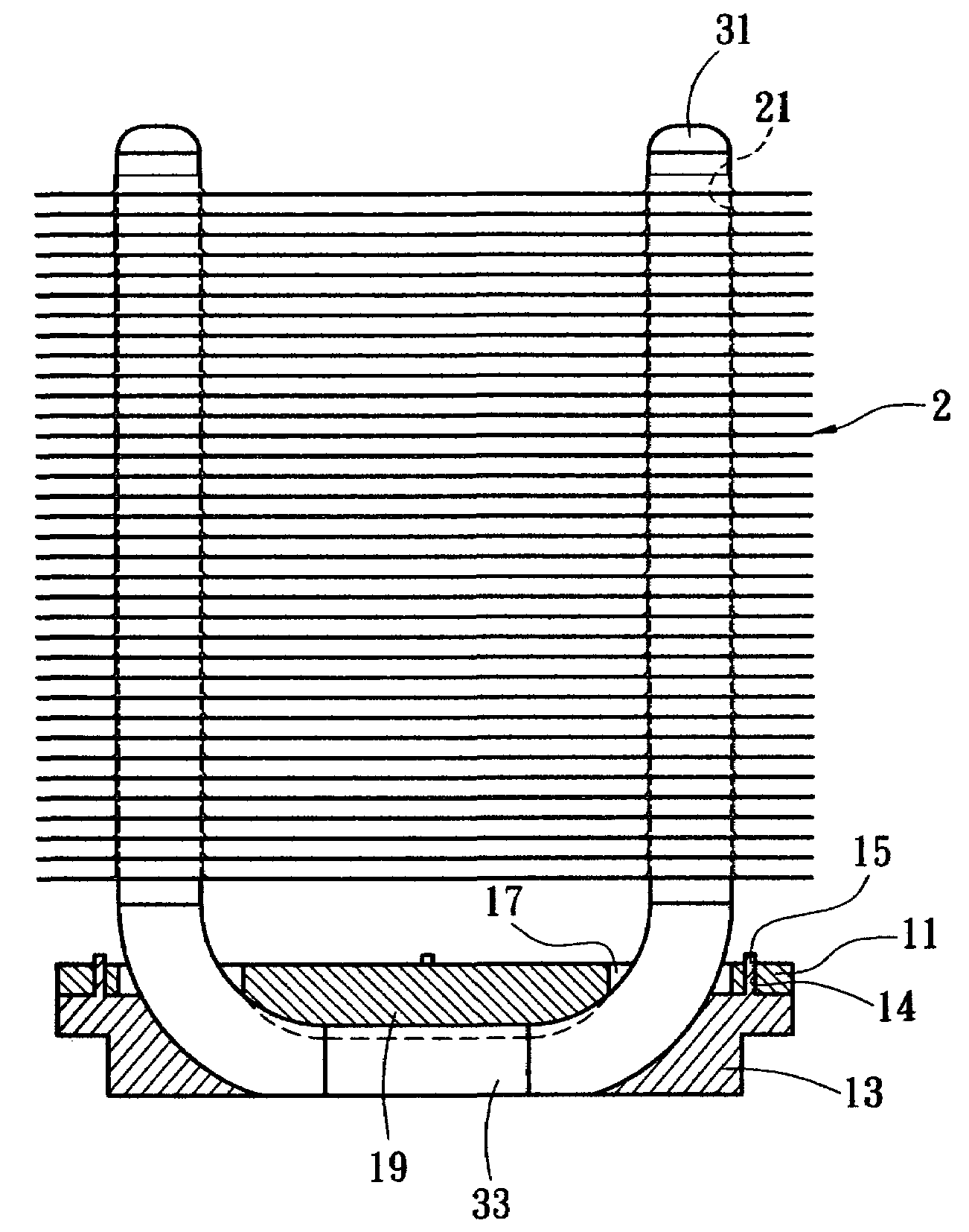
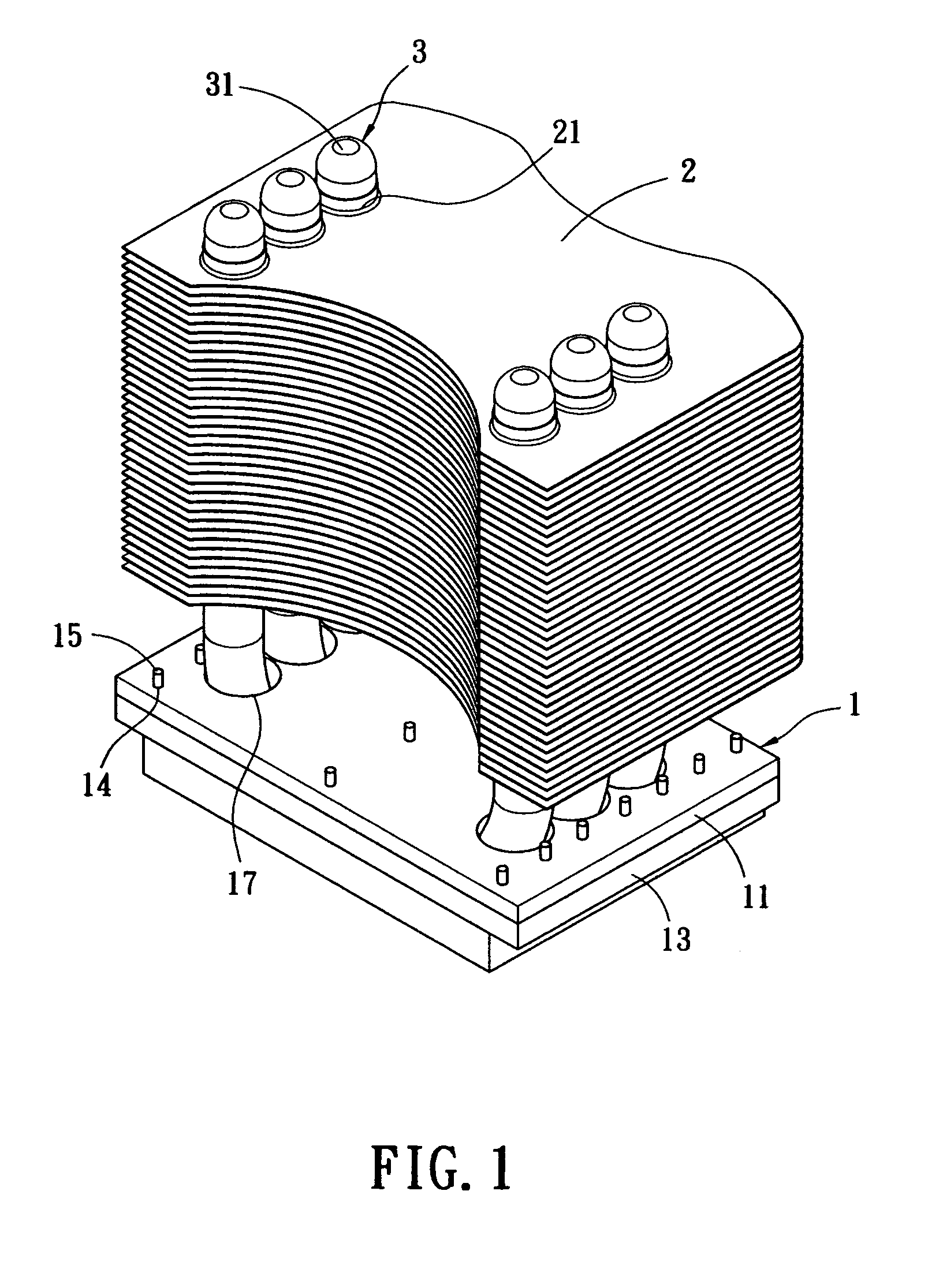
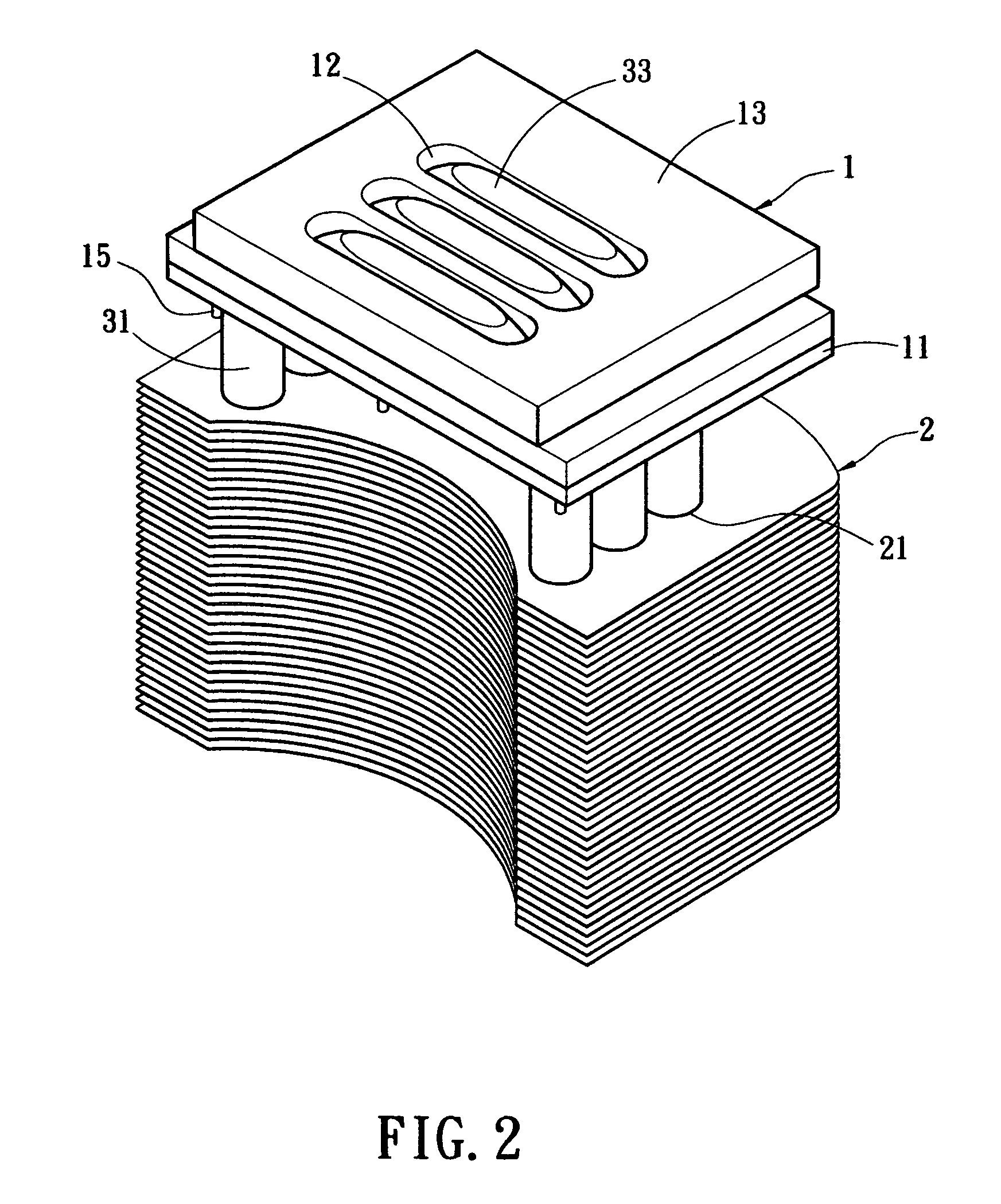
[0022]The present invention provides a method for manufacturing a heat pipe cooling device. A perspective view of the cooling device is illustrated in FIG. 1. As shown, the cooling device includes a plurality of fins 2 stacked on the heat conductor 1. The heat conductor 1 and the fins 2 are made of materials of high heat conductivity, e.g. aluminum or copper. Meanwhile, a plurality of holes 21 is formed on the fins 2 corresponding to the heat pipe 3.

[0023]As shown in FIG. 1, the heat pipe 3 is a U-shaped hollow tube. Any person having ordinary skill in the art would readily appreciate that many other shaped heat pipes are considered within the scope o...


PUM


Abstract

A method for manufacturing a heat pipe cooling device. The heat pipe cooling device includes a U-shaped heat pipe, which is embedded within a heat conductor. The heat conductor includes a rectangular base and an upper cover connected to the base. The base includes many retaining grooves which allow the absorption end of the heat pipe to be disposed therein. The upper cover includes many through holes formed thereon corresponding to the cooling end of the heat pipe. The bottom surface includes many protrusive portions corresponding to the inner side of the absorption end of the heat pipe. Furthermore, the upper cover and the base both include a positioning portion for engaging each other. In this manner, the upper cover is pressed on the cooling end of the heat pipe. The protrusive portion will push the heat pipe to tightly contact with the base. Finally, a planarization process is performed, thereby making the bottom surface of the absorption end and the bottom surface of the heat conductor to form a flat surface.

Description

BACKGROUND OF THE INVENTION[0001]The present invention relates generally to a method for manufacturing a cooling device, and more particularly to a method for manufacturing a cooling device. The heat pipe of the cooling device contacts the heat source directly.[0002]The operation of electronic products, such as personal computer, light emitting laser diode or dynamic transistor, will dissipate heat. For the recently developed electronic devices, more and more heat is generated therefrom. Cooling technology thus becomes one of the key technologies of electronic industry. Typical cooling devices for electronic products are divided into two categories. One type of the cooling devices includes a cooling body installed directly on the heat generating electronic device. The other type of the cooling devices includes a fan for lowering the temperature in the housing of the electronic device.[0003]The cooling device installed on electronic products is normally made of materials of high heat...

Claims


Application Information

Patent Timeline
Patent Type & Authority Patents(United States)
IPC IPC(8): H05K7/20
CPCH01L23/427H01L23/467H01L2924/0002H01L2924/00F28D15/0275F28F1/32
Inventor CHENG, CHIH-HUNG
Owner GOLDEN SUN NEWS TECHN
Why Eureka
Try Eureka