
Method for controlling overcoat recession in a magnetic thin film head

a thin film head and overcoat technology, applied in the direction of maintaining the head carrier alignment, manufacturing tools, instruments, etc., can solve the problems of generating a relatively significant amount of heat, physical contact, damage to the disk surface, etc., and achieves a slight degree of abrasion and softening the surface of the slider material

Inactive Publication Date: 2008-11-25
SAE MAGNETICS (HK) LTD
View PDF21 Cites 5 Cited by
  • Summary
  • Abstract
  • Description
  • Claims
  • Application Information

AI Technical Summary

Benefits of technology

The present invention provides a method for fabricating a slider for hard disk drives that eliminates thermal protrusion of read / write elements and prevents damage to the slider during operation. The method involves a CMP lapping process that uses a compliant porous pad and an aqueous alkaline solution as an etchant / lubricant. This process allows for controlled polishing and recessing of the slider without using abrasive materials. The invention also provides a method for achieving a smooth ABS surface without using a separate contour lapping process. The CMP lapping process removes protrusions and compensates for thermal expansion of the alumina overcoat. The invention achieves these technical effects without adversely affecting the performance of the read / write elements or the air bearing surface of the slider.

Problems solved by technology

During the writing of data on the disk, current flows through the coil in alternating directions, which generates a relatively significant amount of heat.
With flying heights being already extremely low to enable accurate resolution of the narrow disk tracks, thermal protrusion can eventually result in a physical contact between the disk surface and the ABS plane.
This contact can move the slider off its target track, can cause damage to the slider assembly, can damage the disk surface and / or cause a permanent loss of data.
Within the description of the method, the use of rotating lapping plates in the prior art is discussed and it is noted that they produce problems leading to degraded head performance.

Method used


Image

  • Method for controlling overcoat recession in a magnetic thin film head
  • Method for controlling overcoat recession in a magnetic thin film head
  • Method for controlling overcoat recession in a magnetic thin film head

Examples


Embodiment Construction

[0035]The preferred embodiment of the present invention teaches a method of chemical / mechanical (CMP) polishing the ABS of a slider, using a compliant CMP pad whose surface has been rendered porous and formed into a polymeric matrix by a polymeric pre-treatment. The nature of the pad surface and its pre-treatment is fully described below.

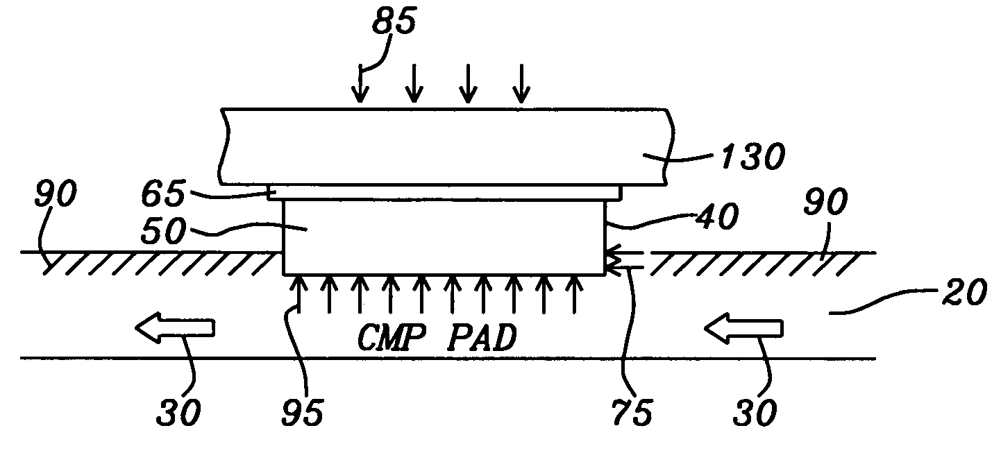
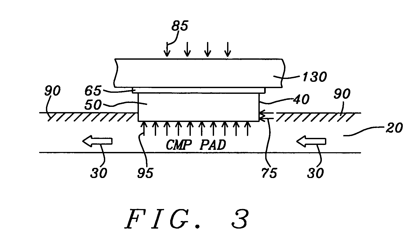
[0036]During the application of the process, the compliant porous CMP pad is additionally sprayed with an aqueous alkali lubricant solution. The alkali lubricant softens surface coatings of Al2O3 that overcoat and cover portions of the slider surface and the moving, compressive contact of the ABS with the surface of the compliant pad is sufficient to remove the softened material in a slow and controlled manner without the use of abrasive polishing compounds. In this way, a controlled recession of the oxide surface coating is obtained and thermal protrusion of the oxide at a later time during actual device operation in a hard disk drive (HDD) is elim...


PUM

PropertyMeasurementUnit
temperaturesaaaaaaaaaa
thicknessaaaaaaaaaa
heightaaaaaaaaaa

Abstract

The overcoat of a slider (alumina) is recessed relative to the slider ABS by a non-abrasive CMP process sufficiently to prevent thermal protrusion of the overcoat during subsequent slider use in a hard disk drive. The CMP process involves the oscillatory and rotational compressional contact between the ABS surface of the slider and a polymerically pre-treated compliant pad that is sprayed by an aqueous alkali lubricating solution having a pH between about 9 and 10. The overcoat is thereby also softened by the lubricating solution and removed by the compressional contact and no use of abrasives is required.

Description

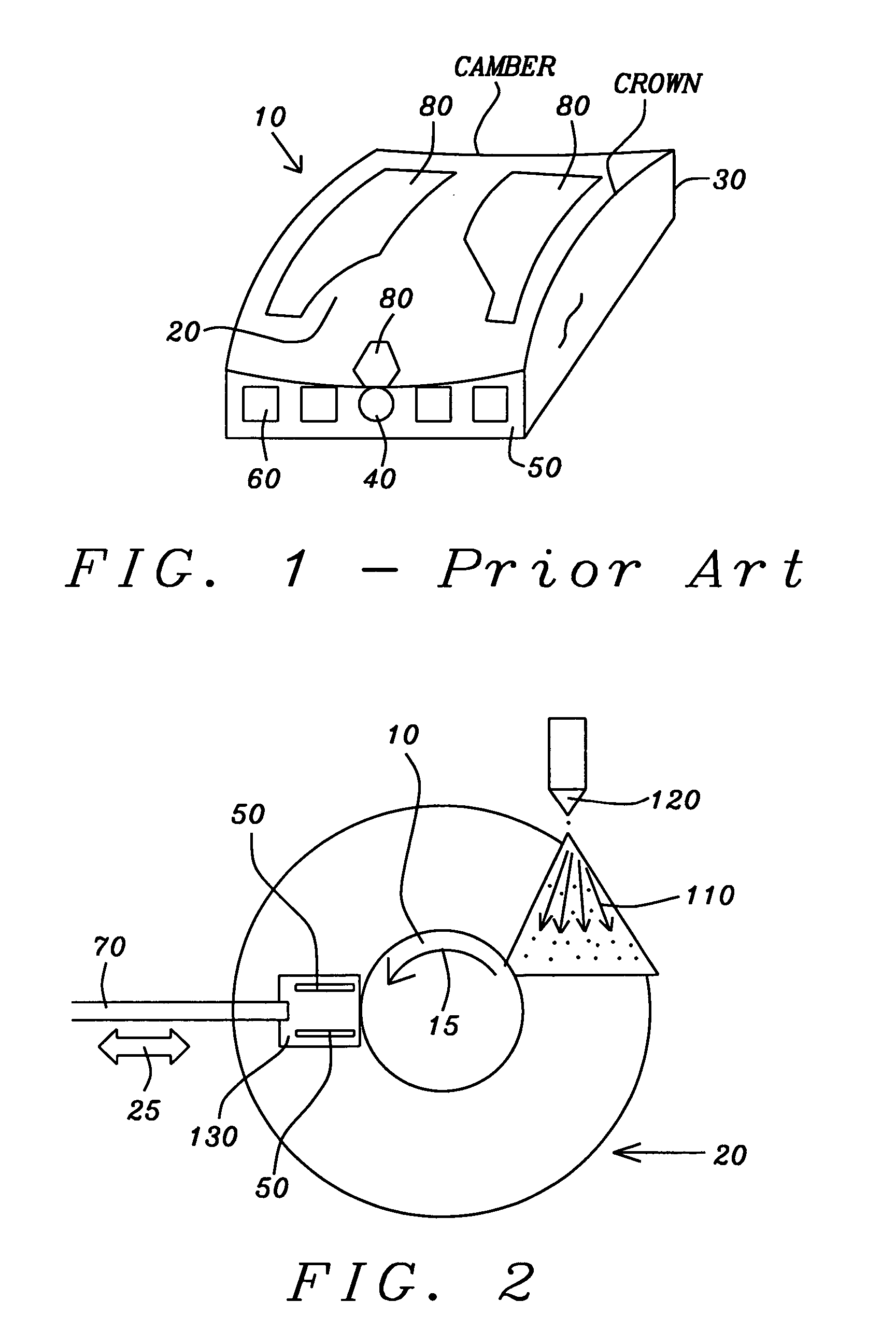
BACKGROUND OF THE INVENTION[0001]1. Field of the Invention[0002]This invention relates to the fabrication of thin film magnetic heads and particularly to a CMP planarization technique for controlling overcoat and pole tip recession of such a head relative to a slider surface.[0003]2. Description of the Related Art[0004]A hard disk drive (HDD) uses an encapsulated thin film magnetic read / write head, called a slider, to read and write data on a magnetic medium or storage disk. FIG. 1 is a schematic illustration of such a device as is used in the prior art and whose improvement is the object of the present invention. The slider (10) has a pre-patterned air-bearing surface (ABS) (20) and is mounted on a head gimbal assembly (HGA) (not shown) that is activated by a mechanism and control circuitry to position the slider at various positions along the magnetic tracks on the disk (not shown). As the disk is rapidly rotated by a spindle motor (not shown), hydrodynamic pressure causes air flo...

Claims


Application Information

Patent Timeline
Patent Type & Authority Patents(United States)
IPC IPC(8): G11B5/127H04R31/00
CPCG11B5/102G11B5/3163G11B5/3169G11B5/3173G11B5/6005G11B5/3136Y10S438/976Y10T29/49043Y10T156/1082Y10T29/49052Y10T29/49041Y10T156/1116Y10T29/49798Y10T29/49046Y10T29/49048G11B5/127G11B5/31G11B21/21
Inventor JOSE, WINSTONAYALA, RUDYMAHADEV, NIRAJ
Owner SAE MAGNETICS (HK) LTD
Learn More