Dynamic spacer for total knee arthroplasty

a technology of a dynamic spacer and a total knee arthroplasty, which is applied in the field of surgical instrumentation systems, can solve the problems of inability to fully extend the knee, and excessive tensile force or excessive looseness, and achieves accurate measurement of flexion-extension gaps, simple construction, and convenient use.

Inactive Publication Date: 2008-11-25
TARABICHI SAMIH
View PDF15 Cites 17 Cited by
  • Summary
  • Abstract
  • Description
  • Claims
  • Application Information

AI Technical Summary

Benefits of technology

[0009]Given the disadvantages of conventional surgical instrumentation systems for measuring flexion-extension gap, the present invention, a dynamic spacer, provides an improved instrumentation system that it easy to use, simple in construction, and accurately measures flexion-extension gaps under repeatable soft tissue tension.
[0010]Unlike conventional spacers, the dynamic spacer applies tension to the soft tissue without relying on the surgeon to repeatedly and accurately distract the knee in flexion and extension. Also, the dynamic spacer does not require removal prior to extension of the knee, thus instead of serving as a guide for distal femur resection, the dynamic spacer accurately measures the difference between the flexion and extension gaps and minimizes the possibility that successive distal femoral cuts will be required to increase the extension gap or the possibility that the distal femoral surface will require packing with bone cement if the extension gap is too large.
[0011]Furthermore, the dynamic spacer can also indicate whether rotation of the distal femur is appropriate. Significant angular deviation of the dynamic spacer in flexion indicating a trapezoidal flexion gap may be corrected by adding external femoral rotation when making the posterior femoral cut. The external rotation improves patellar tracking and minimizes posteromedial wear of the femoral component of the prosthetic knee, particularly in a degenerative valgus knee. Surgeons employing conventional spacers must rely on their subjective observation to determine the appropriateness of femoral rotation. However, accurate measurements of deviations from rectangular flexion gap can be determined when employing the dynamic spacer of the present invention.

Problems solved by technology

Such tensioning is necessary because tendons and ligaments are relatively inextensible, and the spatial differences between the prosthetic knee and the natural joint may result in excessive tensile forces or excessive looseness.
If an implant is selected to fit the flexion gap and the flexion gap exceeds the extension gap, the knee will be incapable of full extension.
Conversely, if the extension gap exceeds the flexion gap, the knee will hyper-extend and will be unstable in full extension.
If an implant is selected to fit the extension gap, similar problems arise in flexion, as does the risk of dislocation
Distraction clamps are often quite large, particularly if they also perform measurement functions, and clamps have the tendency to damage the bone surfaces in which they make contact.
Also, the surgeon must tension the clamps manually and ensure equal tension across the lateral-medial plane, which often proves to be a difficult process.
The conventional tensor is not very practical due to the device's complexity and due to difficulties associated with its use.

Method used


Image

  • Dynamic spacer for total knee arthroplasty
  • Dynamic spacer for total knee arthroplasty
  • Dynamic spacer for total knee arthroplasty

Examples


Embodiment Construction

[0016]In the following detailed description of the preferred embodiments, reference is made to the accompanying drawings, which form a part hereof, and in which are shown by way of illustration specific embodiments in which the invention may be practiced. It is to be understood that other embodiments may be utilized and structural changes may be made without departing from the scope of the present invention.

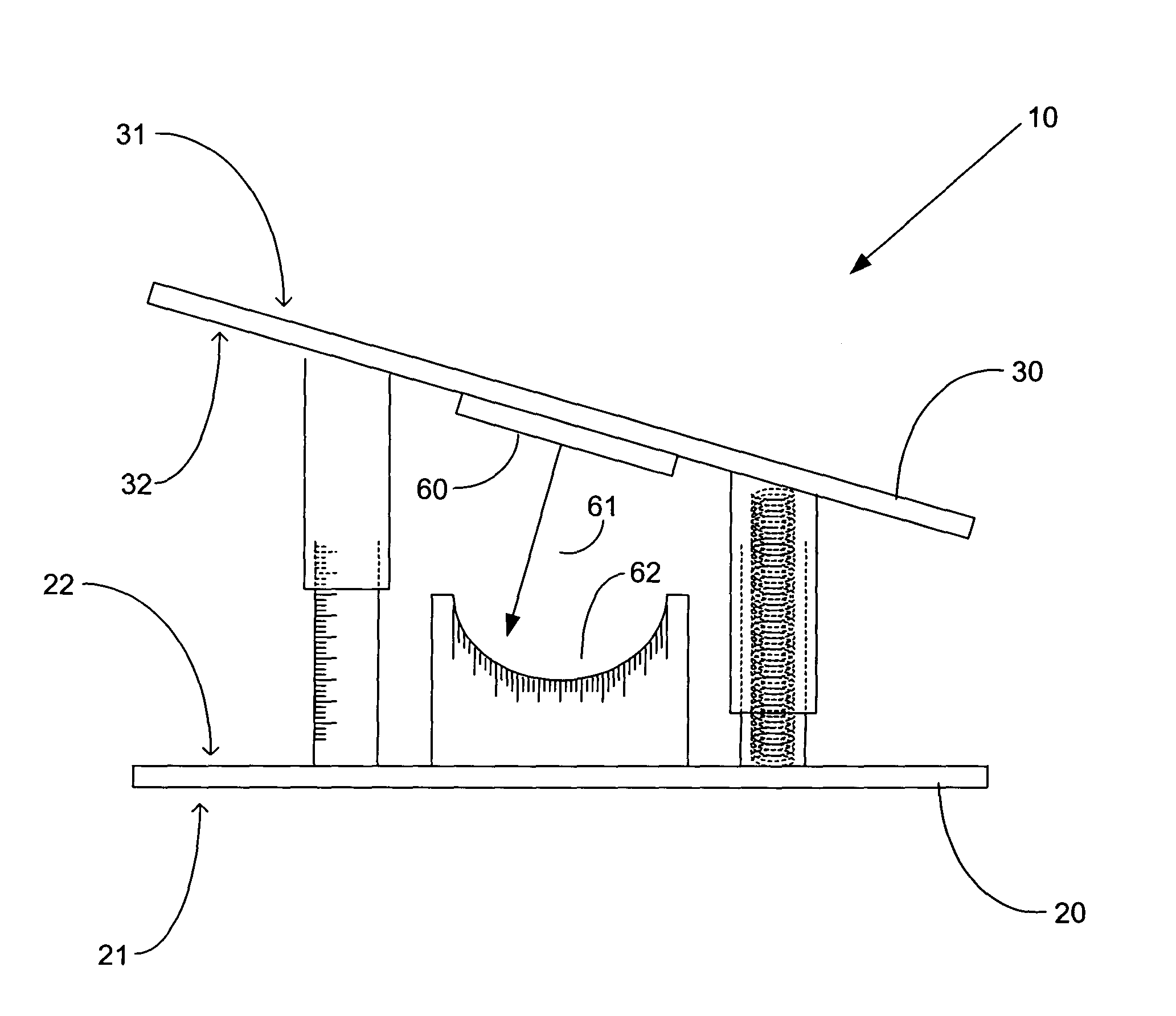
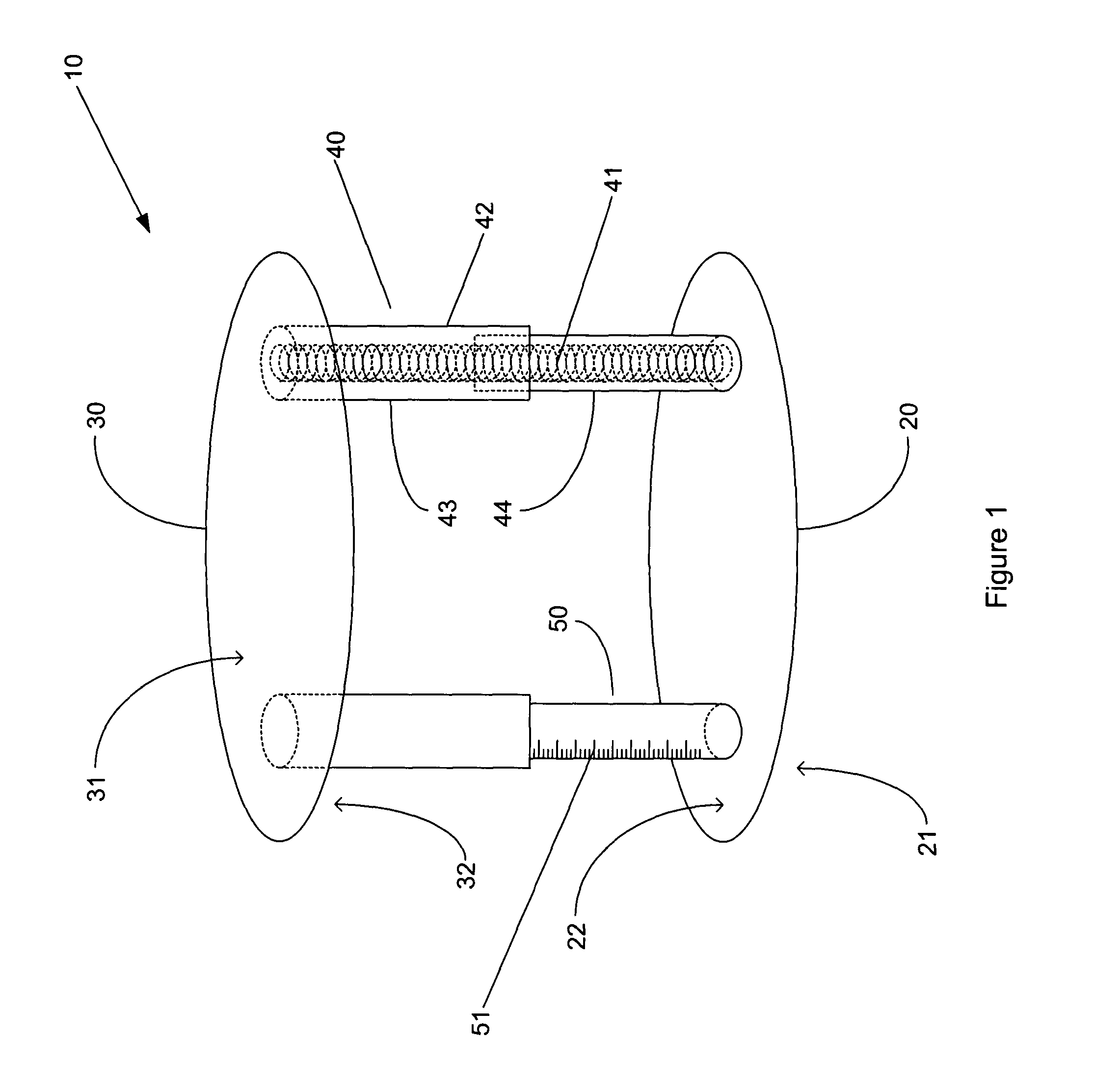
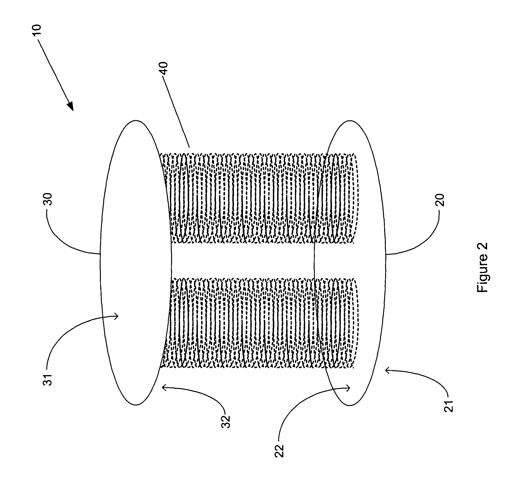
[0017]FIG. 1 illustrates one preferred embodiment of the present invention. The dynamic spacer 10 comprises a first planar member 20 having a lower tissue engaging surface 21 and an upper tensioning surface 22 and a second planar member 30 having an upper tissue engaging surface 31 and a lower tensioning surface 32. The shape of the first and second planar members 20, 30 is substantially oval, however, any suitable shape that can be inserted into the surgically prepared knee capsule may be employed. The first and second planar members 20,30 may be constructed of any suitable mate...


PUM


Abstract

A dynamic spacer is provided for measuring flexion-extension gap during total knee arthroplasty. The dynamic spacer includes a first planar member having a lower tissue engaging surface, and a second planar member having an upper tissue engaging surface. A tensioner is disposed between the first planar member and the second planar member for applying a tensile force acting upon the first and second planar members. The tensioner is attached to the first and second planar members, such that the first planar member is held substantially parallel to the second planar member in the absence of compressive load. The dynamic spacer allows for accurately measuring flexion-extension gaps and angular deviation in flexion indicating the appropriateness of femoral rotation.

Description

STATEMENT REGARDING FEDERALLY SPONSORED RESEARCH OR DEVELOPMENT[0001]Not ApplicableFIELD OF THE INVENTION[0002]The present invention relates to a surgical instrumentation system used during total knee arthroplasty.BACKGROUND OF THE INVENTION[0003]Surgical techniques for total knee arthroscopy (“TKA”) involve the measurement of the flexion and extension gaps. Soft tissue imbalance and bony misalignment can lead to malfunction and failure, thus the accurate measurement of the flexion and extension gaps is critical to a successful TKA procedure.[0004]Surgical techniques for TKA typically begin with resection of the proximal tibia, and the balancing of the soft tissues of the knee in extension. The knee is then placed into flexion and a cutting block employed to obtain a rectangular flexion gap while the knee is distracted in flexion. After measuring the flexion gap, the distal femur is then resected. The knee is placed back into extension and the extension gap is measured and compared ...

Claims


Application Information

Patent Timeline
Patent Type & Authority Patents(United States)
IPC IPC(8): A61B5/103A61B5/117A61B17/02A61B19/00
CPCA61B5/1071A61B17/025A61B5/4528A61B2017/0268A61B2019/464A61B2090/064
Inventor TARABICHI, SAMIH
Owner TARABICHI SAMIH
Why Eureka
Try Eureka