Process for transferring a coating onto a surface of a lens blank

a technology of coating and lens blank, which is applied in the field of coating transfer process, can solve the problems of difficult manufacturing and handling of preforms less than 500 microns thick, and achieve the effects of no interference fringe, low interference fringe, and good optical quality

Inactive Publication Date: 2008-11-25
ESSILOR INT CIE GEN DOPTIQUE
View PDF40 Cites 15 Cited by
  • Summary
  • Abstract
  • Description
  • Claims
  • Application Information

AI Technical Summary

Benefits of technology

[0044]An important feature of the process of the present invention is that the transfer of the coating onto the geometrically defined surface of the lens blank is performed without any substantial compression of the blank and thus without any risk of deformation of the blank geometry and in particular of the geometrically defined surfaces thereof.
[0062]For a coating transfer to a spherical back side of a lens or lens blank, in order to avoid distortions, in particular when using a flexible mold part, the base curvature (BC) of the flexible mold part (front side) must be slightly higher than the base curvature (BL) of the geometrically defined surface of the lens or the lens blank on which the coating is to be transferred. However, BC shall not be too high in order to avoid cracking of the coating during the transfer process or an optical power outside tolerance of Z801 after the transfer.
[0092]The glue or adhesive may be any curable glue or adhesive, preferentially a thermally curable or photocurable, in particular UV curable, glue or adhesive that will promote adhesion of the coating to the optical surface of the blank without impairing the optical properties of the finished lens.
[0102]The final lenses obtained by the method of the invention have very good optical quality and they have no or very low level of interference fringes.

Problems solved by technology

In general, it is difficult to manufacture and handle preforms that are less than 500 microns thickness.

Method used


Image

  • Process for transferring a coating onto a surface of a lens blank
  • Process for transferring a coating onto a surface of a lens blank
  • Process for transferring a coating onto a surface of a lens blank

Examples


example 1

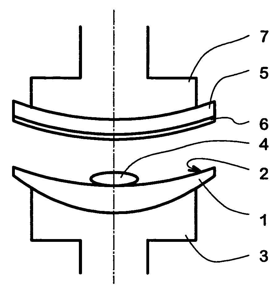
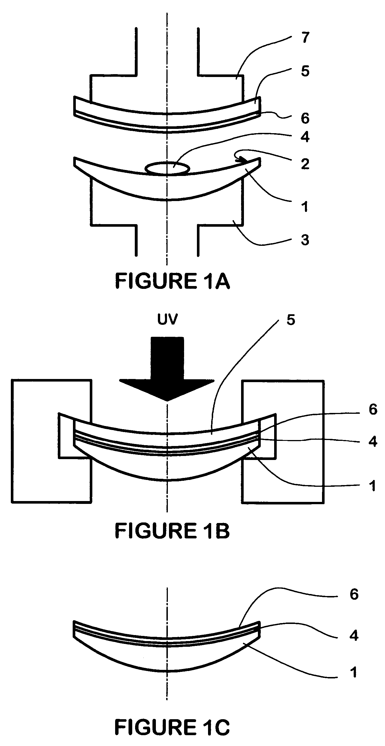
[0136]The convex side with base curve 6 of a flexible mold part made of polycarbonate (PC) and having a thickness of 1 mm is pre-coated with HMC coating. Orma SF(1) lenses were surfaced on their back side to different curves of surface as indicated in Table I below. Then the HMC coating on the mold part was transferred to the surface back side of the lenses in the manner described in connection with FIGS. 1A to 1C. The glue used was a UV curable glue OP-21 from DYMAX Inc. After the curing, the mold part was removed from the lenses and the lenses were recovered with the coating stuck on their back sides. The finished coated lenses have very good optical properties and the transfer coatings show no cracks even though the coatings were deformed to a certain level during the transfer.

[0137](1) SF: Semi-finished

[0138]

TABLE ICoating PC moldOrma lens withCoatingpartdifferent back curveBLRBLrtransfer resultsSpheric CV 6 Base5 base with toric 0.955.9ExcellentSpheric CV 6 Base5 base with tori...

example 2

[0139]Example 1 was reproduced but using a soft silicone mold part instead of a PC mold part. The resulting final coated lenses exhibited very good optical properties and the coatings do not show any cracks even though the coatings were deformed to a certain level during the transfer.

[0140]The silicone mold part used was made from POR-A-MOLD 2030 of Synair Inc. The silicone monomer was filled into a glass mold and cured at room temperature for 24 hours to get a front 4 base curve carrier with thickness of 2.5 mm. The obtained silicon has 900% elongation and 28 of Shore A Hardness.

example 3

[0141]Orma SF lenses were ground to different levels on their back side with 6 base curves and coatings were transferred to the back side of the lenses as disclosed in example 1. After transfer of the coating, the finished coated lenses were checked by transmission T, Haze with Haze-Gard Plus (BYK Gardner) (compared to the sample before transfer of the coating). Then, the lens were checked again in Arc lamp to see if there was any grinding lines seen by the eye. Grinding process and results are given in Table II below:

[0142]

TABLE IIHMC film transferred onto grind surface of the lens (without polishing)RoughnessbeforetransferringtheRefractiveT %Hazecoating(s)index ofSeen in ArcLens typeGrind process type(before)(before)(Sq)glueT % (after)Haze (after)lampOrma ®V95 + fine w / 9090 0.4 μm1.505980.73Nothingstandard process(1)PCGemini913.50.03 μm1.505950.42NothingProcess(2)

[0143]Sq: Quadratic mean of the deviations from the mean

[0144]Sq=1NM⁢∑x=1N⁢⁢∑y=1M⁢⁢Zx,y2

[0145]Computes the efficient va...


PUM

PropertyMeasurementUnit
thicknessaaaaaaaaaa
thicknessaaaaaaaaaa
thicknessaaaaaaaaaa

Abstract

A process for transferring a coating onto at least one optical surface of a lens blank which comprises:providing a lens blank having at least one geometrically defined surface;providing a support having an internal surface bearing a coating and an external surface;depositing on said geometrically defined surface of said lens blank or said coating a pre-measured amount of a curable glue;moving relatively to each other the lens blank and the support to either bring the coating into contact with the curable glue or bring the curable glue into contact with the geometrically defined surface of the lens blank;applying a sufficient pressure onto the external surface of the support so that the thickness of a final glue layer after curing is less than 100 micrometers;curing the glue; andwithdrawing the mold part to recover the lens blank with the coating adhered onto its geometrically defined surface.

Description

[0001]This application is a national phase application under 35 U.S.C. 371 of PCT Application No. PCT / EP02 / 07239 filed 1 Jul. 2002, which claims priority to U.S. application Ser. No. 09 / 899,367 filed 2 Jul. 2001, the contents of which are incorporated herein by reference in their entirety.BACKGROUND OF THE INVENTION[0002]The present invention relates to an improved process or method for transferring a coating onto at least one surface of a lens blank which can be implemented in a short period of time without any risk of deformation of the lens blank.[0003]It is a common practice in the art to coat at least one face of an ophthalmic lens with several coatings for imparting to the finished lens additional or improved optical or mechanical properties.[0004]Thus, it is usual practice to coat at least one face of an ophthalmic lens, typically made of an organic glass material, with successively, starting from the face of the lens, an impact resistant coating (impact resistant primer), a...

Claims


Application Information

Patent Timeline
Patent Type & Authority Patents(United States)
IPC IPC(8): B29D11/00G02B1/11B29C35/08B29C63/16B29C63/22B29C63/48B29C65/00B29C65/14B29C65/48G02B1/10
CPCB29C63/16B29C65/1406B29C65/4845B29C66/45B29C66/80B29C66/81267B29C66/81422B29C66/81423B29C66/81455B29D11/0073B29C65/1435B29C65/1483B29C65/483B29C63/22Y10T156/1744B29C2035/0827B29C2063/485B29K2669/00B29K2869/00B29L2011/0016B29C65/4835B29C65/4865B29K2995/0089B29K2995/007B29C66/7315B29C66/81264B29C66/73161B29K2995/0072B29C65/52B29C66/301B29C66/452B29C66/545B29C66/83221B29C66/7352B29C66/73921B29C66/8122B29K2995/0027B29C66/7338B29C66/71Y10T428/31507B29C66/1122B29D11/00009B29K2069/00
Inventor JIANG, PEIQIADILEH, FADI O.TURSHANI, YASSIN YUSEFWEBER, STEVEN
Owner ESSILOR INT CIE GEN DOPTIQUE
Why Eureka
Try Eureka