Image heating apparatus

a heating apparatus and image technology, applied in the field of image heating apparatus, can solve the problems of non-uniformity, deterioration of image quality on recording materials, etc., and achieve the effect of suppressing the occurrence of image heating defects and reducing the force required for rotating a first belt and a second bel

Inactive Publication Date: 2008-11-25
CANON KK
View PDF15 Cites 48 Cited by
  • Summary
  • Abstract
  • Description
  • Claims
  • Application Information

AI Technical Summary

Benefits of technology

[0010]Accordingly, it is a principal object of the present invention to provide an image heating apparatus in which forces required for rotating a first belt and a second belt are reduced, and in addition, the occurrence of the image heating defect can be suppressed.

Problems solved by technology

In the case of the roller fixing type, this necessitates increase of the roller diameter with the result of upsizing of the fixing device.
Non-uniformness arises in the pressure in the fixing nip due to the emboss structures of the low friction sheets, with the result of appearance of stripes by the different glossiness.
Thus, the image quality on the recording material is deteriorated.

Method used


Image

  • Image heating apparatus
  • Image heating apparatus
  • Image heating apparatus

Examples


embodiment 1

(1) Image Forming Station:

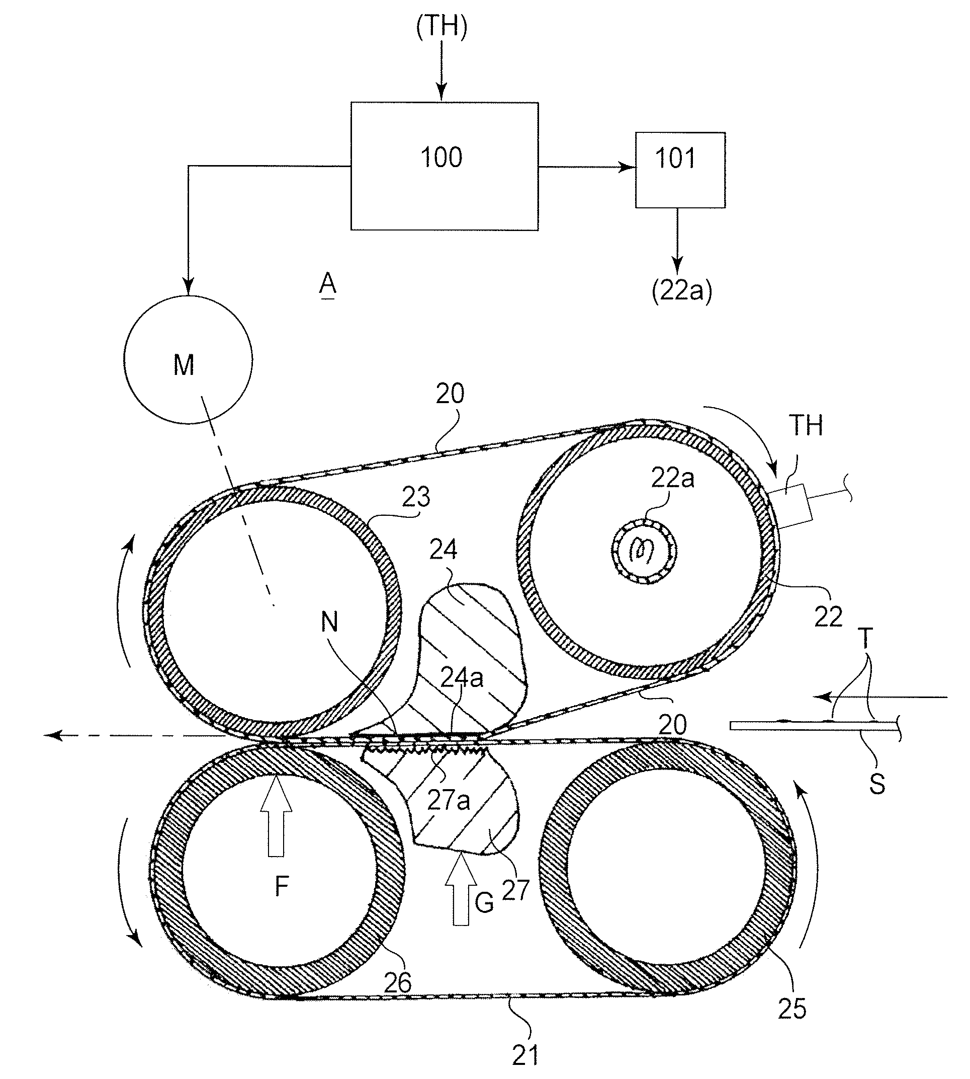
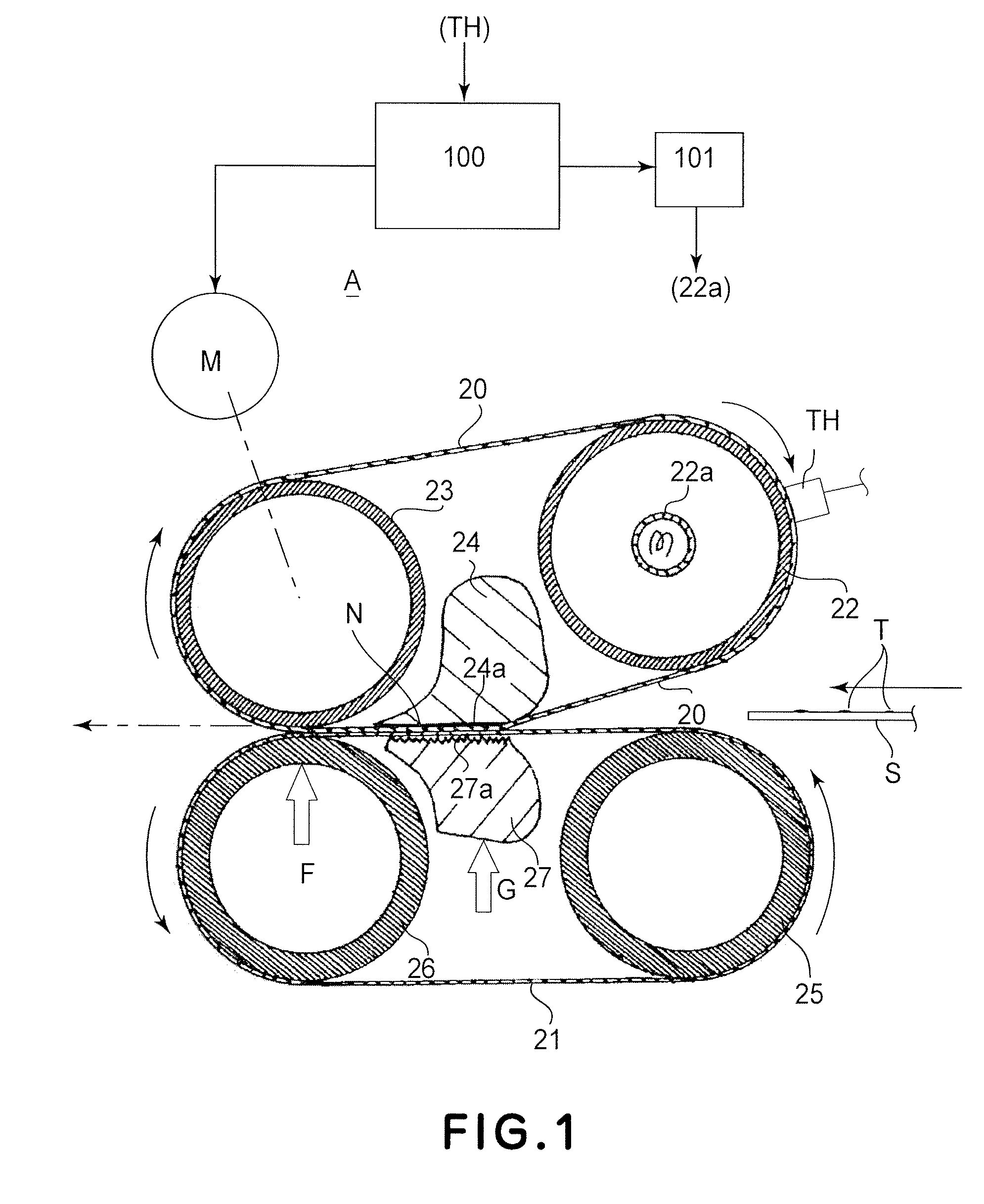
[0018]FIG. 4 is a schematic sectional view illustrating structures of a fixing device A which is an example of an image forming apparatus according to an embodiment of the present invention.

[0019]The image forming apparatus 1 of this example is an electrophotographic type laser beam printer comprising a photosensitive drum 2 (image bearing member) for bearing a latent image. The photosensitive drum 2 is rotated at a predetermined speed in the clockwise direction indicated by an arrow, and the outer surface thereof is electrically charged by a charger 3 to a uniform predetermined potential of the predetermined polarity. The uniformly charged surface is exposed to laser scanning exposure light 5 modulated in accordance with image information by a laser scanner (optical apparatus) 4. By this, an electrostatic latent image corresponding to the image information is formed on the surface of the photosensitive drum 2. The electrostatic latent image is developed by...

embodiment 2

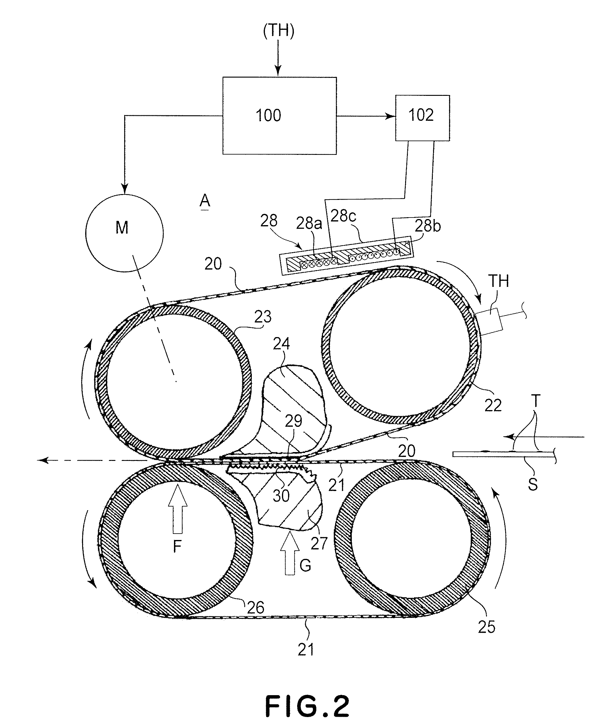
[0053]FIG. 2 is a schematic sectional view of a major part of the fixing device A according to Embodiment 2 of the present invention. In this embodiment, an electromagnetic induction heating type heating source (induction heating member, excitation coil or the like) exhibiting a high energy efficiency, is used as the heating means for the fixing belt 20. Induction heating member 28 comprises an induction coil 28a, an excitation core 28b and a coil holder 28c holding them. The induction coil 28a comprises a litz wire and is a flat oval coil which is disposed in recesses of an excitation core 28b having a horizontal E-shape cross-section. The excitation core 28b is made of ferrite, permalloy or the like which has a high magnetic permeability and a low remanent flux density, and therefore, the loss by the induction coil 28a and the excitation core 28b can be suppressed, so that fixing belt 20 can be efficiently heated.

[0054]Since the base layer of the fixing belt 20 of the embodiment i...

embodiment 3

[0064]In this embodiment, the elastic layer of the fixing belt 20 has a thickness of 300 μm. The structures of this embodiment are the same as those of Embodiment 2.

[0065]When the thickness of the elastic layer of the fixing belt 20 is large, the thermo-conductivity for the fixing operation is low with the result of poor heat followability of the fixing surface, which deteriorates the quick start property and also foster the tendency of non-uniform fixing property. Particularly, since the fixing belt 20 is opposed to the image on the recording material, the thickness of the elastic layer of the fixing belt 20 is preferably not more than 500 μm in consideration of the quick start property, the prevention of the fixing non-uniformity. However, if the thickness of the elastic layer of the fixing belt 20 is too small, it is difficult to smooth out the pressure unevenness with the result of tendency of the influence of the surface property of the pad or the like to which the inner surfac...


PUM


Abstract

An image heating apparatus includes a first belt contactable to an image on a recording material to heat the image; a second belt for forming a nip with the first belt; a first pressing pad for pressing the first belt in the nip; a second pressing pad for pressing the second belt toward the first pressing pad, wherein the first pressing pad has a surface roughness Rz of not more than 20 μm, and the second pressing pad has a surface roughness Rz of 50-300 μm.

Description

FIELD OF THE INVENTION AND RELATED ART[0001]The present invention relates to an image heating apparatus for heating an image formed on a recording material. Examples of the image heating apparatus include a fixing device for fixing an unfixed image on the recording material and a glossiness improvement apparatus for re-heating the fixed image on the recording material. Such a fixing device and / or a glossiness improvement apparatus are usable with an image forming apparatus such as a copying machine, a printer or a facsimile machine.[0002]In an image forming apparatus such as an electrophotographic apparatus or an electrostatic recording apparatus, a toner image is formed on a recording material (sheet) and is heated and pressed so that it is fixed. As for the fixing device, a roller fixing type is known in which a pressing roller is pressed against a fixing roller containing a heater therein to form a fixing nip.[0003]In order to increase the speed of image formation or raising the ...

Claims


Application Information

Patent Timeline
Patent Type & Authority Patents(United States)
IPC IPC(8): G03G15/20
CPCG03G15/206G03G2215/2016G03G2215/2048G03G2215/2022
Inventor TAKADA, SHIGEAKIJINZAI, MAKOTOHASEGAWA, KAZUHIRONAKAMOTO, IKUOHAYASHI, YASUHIROMATSUURA, DAIGOKAJI, KEIGOKOMIYAMA, HIROSHIHARA, NOBUAKI
Owner CANON KK
Why Eureka
Try Eureka