
Internal combustion engine having a fuel injection system

Active Publication Date: 2008-12-02
SCION SPRAYS LTD
View PDF53 Cites 14 Cited by
  • Summary
  • Abstract
  • Description
  • Claims
  • Application Information

AI Technical Summary

Benefits of technology

[0038]Internal combustion engines that make use of embodiments of the invention can do away with complicated, heavy and expensive fuel injection systems. Instead, they may make use of a cheaper and simpler system that does not require the pressure within the inlet passage to be monitored or the provision of a fuel pump and pressure regulator to maintain a constant pressure differential between the fuel and the charge air. Rather, the fuel injector of the current invention dispenses a known quantity of fuel at a fixed flow rate independent of the pressure of the charge air. The vacuum drawn in the combustion chamber by piston motion while the inlet valve is closed is used to draw in air through the mixing chamber to entrain injected fuel and atomise the fuel as the fuel and air mixture is drawn through the atomising nozzle. There is no need for an air pump as used in known gasoline direct injection engines. The ability to deliver fuel in this way also allows a simpler apparatus for dispersing the fuel in the charge air and the use of low cost effective atomisation processes without effecting the accurate fuel quantity being delivered, so allowing simple small engines to benefit from well atomised accurate full flow rates.

Problems solved by technology

It is a problem to ensure that such fuel is properly atomised.
Most fuel injection system are designed to meter fuel accurately and are not fuel atomisation devices.
This is difficult with conventional injectors since if the atomisation process has any variable effect on the pressure difference across the injector this can alter the flow rate of fuel through the injector and cause incorrect fuel quantities to be delivered to the engine.
Therefore, choosing an effective atomisation process is very limited with the conventional fuel injection systems and the current “state of the art” injection systems overcome this problem by using a complex highly controlled high pressure fuel system where the high kinetic energy in the fuel can aid atomisation.
However, there are many other applications for internal combustion engines where such a level of sophistication is not appropriate and too costly.
For instance, small single cylinder engines as used for lawn mowers, chain saws, small generators, mopeds, scooters, etc are built to very tight cost targets and so cannot afford the cost of a sophisticated fuel injection system nor the additional power required to run a fuel pump.

Method used


Image

  • Internal combustion engine having a fuel injection system
  • Internal combustion engine having a fuel injection system
  • Internal combustion engine having a fuel injection system

Examples


first embodiment

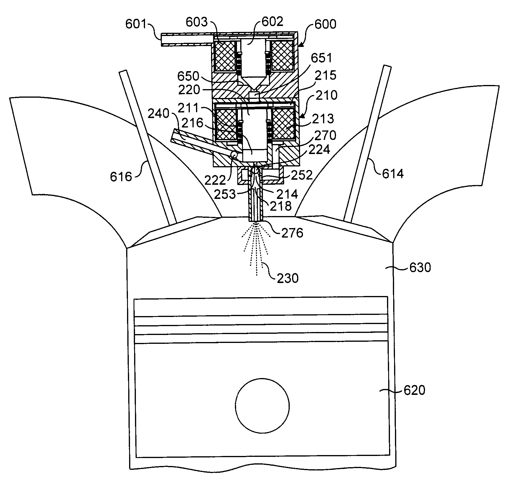
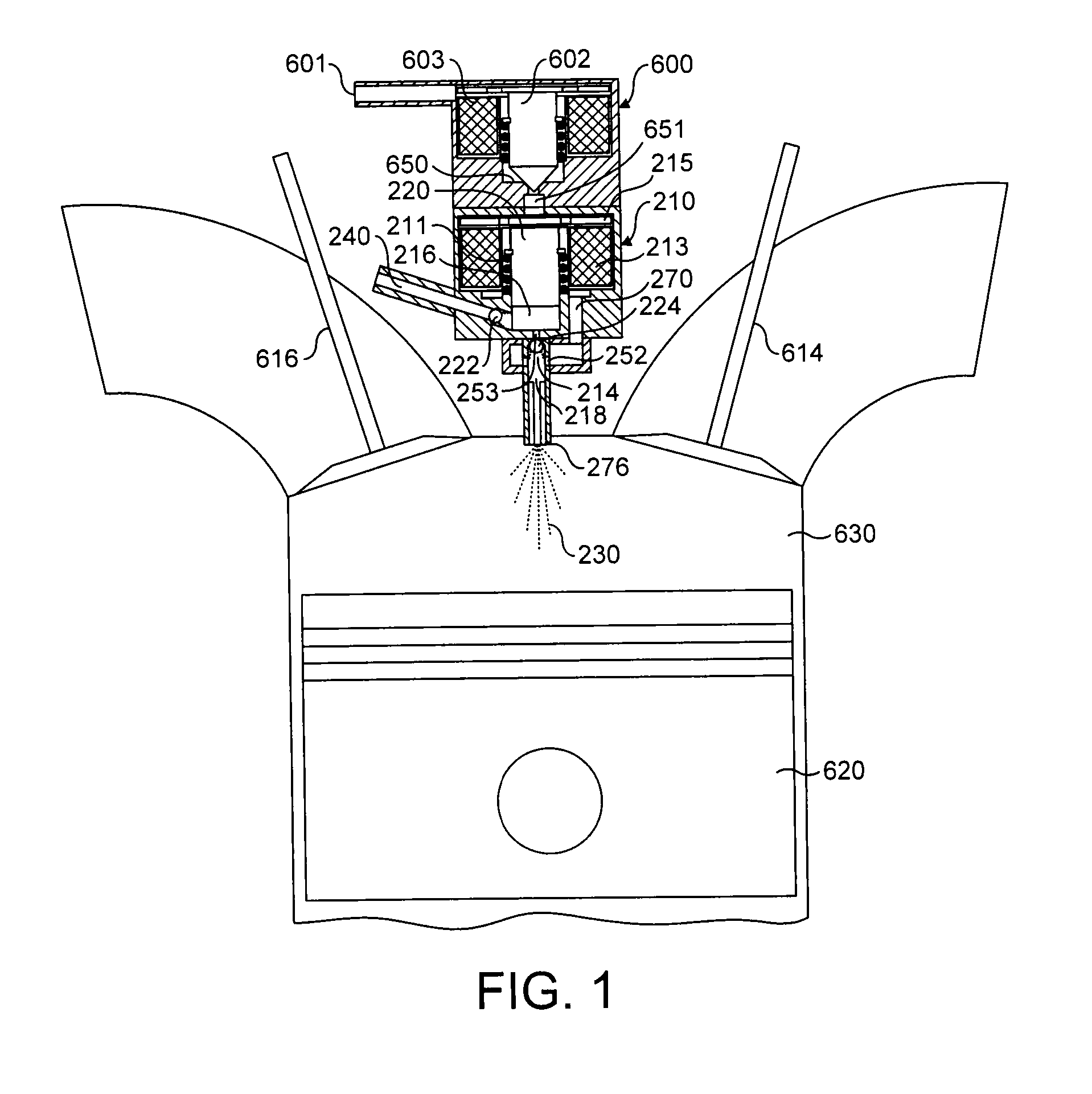
[0044]the invention uses a fuel injector 210 and nozzle 276. The fuel injector 210 provides direct injection of fuel into the combustion chamber 630 of an engine. FIG. 1 shows an internal combustion engine in which a piston 620 cooperates with a cylinder to define a combustion chamber 630. Also shown are an inlet valve 614 controlling flow of charge air into the combustion chamber 630 and an exhaust valve 616 controlling flow of exhaust gas from the combustion chamber 630. A sonic nozzle 276 of the fuel injector 210 is arranged to dispense fuel directly into the combustion chamber 630 of the engine. The fuel injector 210 comprises a fuel inlet 240, a fuel outlet 214 and a fuel chamber 216. The fuel inlet 240 of the fuel injector 210 is connected to a supply of fuel and communicates via spring-loaded one-way inlet valve 222 with the fuel chamber 216. A second spring-loaded one-way outlet valve 224 controls the flow of fuel out of the fuel chamber 216 to the fuel outlet 214.

[0045]The ...

second embodiment

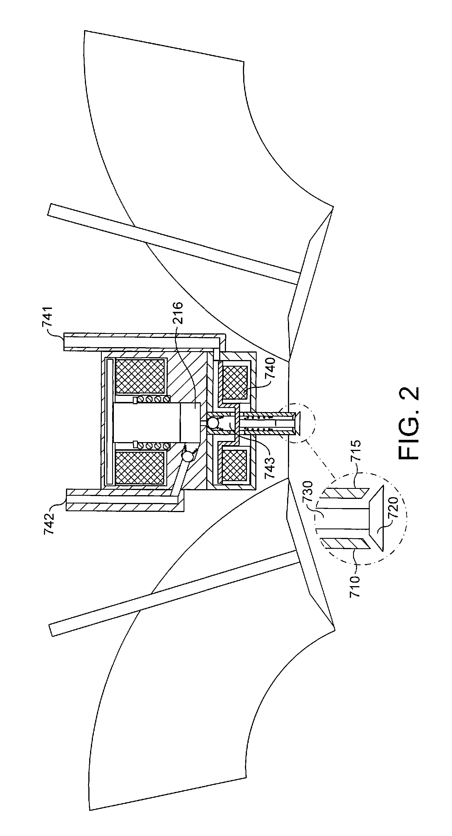
[0060]FIG. 2 shows the invention. This is similar to the embodiment shown in FIG. 1. The fuel injector is located for direct injection of fuel into the combustion chamber of the engine. However, this embodiment includes a different type of sonic nozzle. In this case, the sonic nozzle consists of an outer tube 710 through which fuel entrained in air (or exhaust gases) flows. A pintle 720 is provided across the end of the tube inside the combustion chamber. The closure is connected to an actuating rod 730 located centrally of the outer tube 710. Importantly, the pintle 720 abuts against the outer tube 710. The abutting surfaces of both the pintle 720 and the outer tube 710 are chamfered.

[0061]Fuel supplied by supply line 742 is dispensed from the fuel mixing chamber 216 of the injector 210. At the same time the pintle closure is opened allowing fuel and air to be dispensed into the combustion chamber 630. Air (or exhaust gases) flows through passage 741 to entrain the dispersed fuel i...


PUM


Abstract

With reference to Figure, the present invention provides a fuel injection system for an internal combustion engine which delivers fuel to be mixed with charge air for subsequent combustion in a combustion chamber of the internal combustion engine. The fuel injection system comprises a fuel injector which functions as a positive displacement pump and dispenses in each operation thereof a set quantity of fuel;a mixing chamber into which the fuel injector dispenses fuel; and a gas supply passage for supplying gas to the mixing chamber to entrain the fuel dispensed into the mixing chamber in a flow of gas which passes through the mixing chamber into the combustion chamber. The mixing chamber is connected to the combustion chamber to deliver fuel and gas into the combustion chamber separately from the charge air and a depression in the combustion chamber is used to draw gas through the gas supply passage into the combustion chamber. An inlet valve controls flow of charge air into the combustion chamber and the inlet valve is kept closed for an initial part of an intake stroke of the engine so that the depression is created in the combustion chamber.

Description

BACKGROUND OF THE INVENTION[0001]The present invention relates to an internal combustion engine having a fuel injection system.[0002]Most internal combustion engines in automobiles currently use fuel injection systems to supply fuel to the combustion chambers of the engine. Some fuel injection systems have fuel injectors which inject fuel directly into a combustion chamber of an engine. It is a problem to ensure that such fuel is properly atomised.[0003]Most fuel injection system are designed to meter fuel accurately and are not fuel atomisation devices. It is recognised that a finely atomised fuel spray will improve air fuel mixing and will help reduce engine emissions. It is therefore advantageous to incorporate an atomisation feature into the fuel injector. This is difficult with conventional injectors since if the atomisation process has any variable effect on the pressure difference across the injector this can alter the flow rate of fuel through the injector and cause incorrec...

Claims


Application Information

Patent Timeline
IPC IPC(8): F02M37/04F02M23/00
CPCF02M51/04F02M57/027F02M61/08F02M61/184F02M69/045
Inventor ALLEN, JEFFREY
Owner SCION SPRAYS LTD
Learn More