Stormwater treatment system and method

a technology of stormwater treatment and separator, which is applied in the direction of water cleaning, separation process, liquid displacement, etc., can solve the problems of reducing the efficiency of the separator in removing solids from stormwater, reducing the length, etc., and achieves the effect of improving water quality, efficient sediment removal, and increasing the length of the separator

Active Publication Date: 2008-12-02
LANE ENTERPRISES
View PDF25 Cites 17 Cited by
  • Summary
  • Abstract
  • Description
  • Claims
  • Application Information

AI Technical Summary

Benefits of technology

[0007]The invention is an improved water quality separator that more efficiently rem

Problems solved by technology

Stormwater runoff is a major source of water pollution of lakes, rivers, and streams.
The length of the upstream or expansion portion of the sediment chamber required to convert turbulent flow into laminar flow re

Method used


Image

  • Stormwater treatment system and method
  • Stormwater treatment system and method
  • Stormwater treatment system and method

Examples


Embodiment Construction

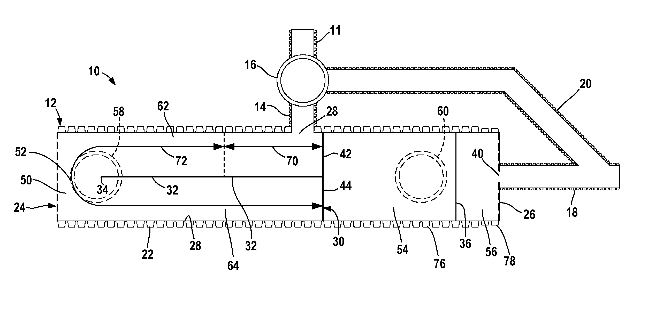
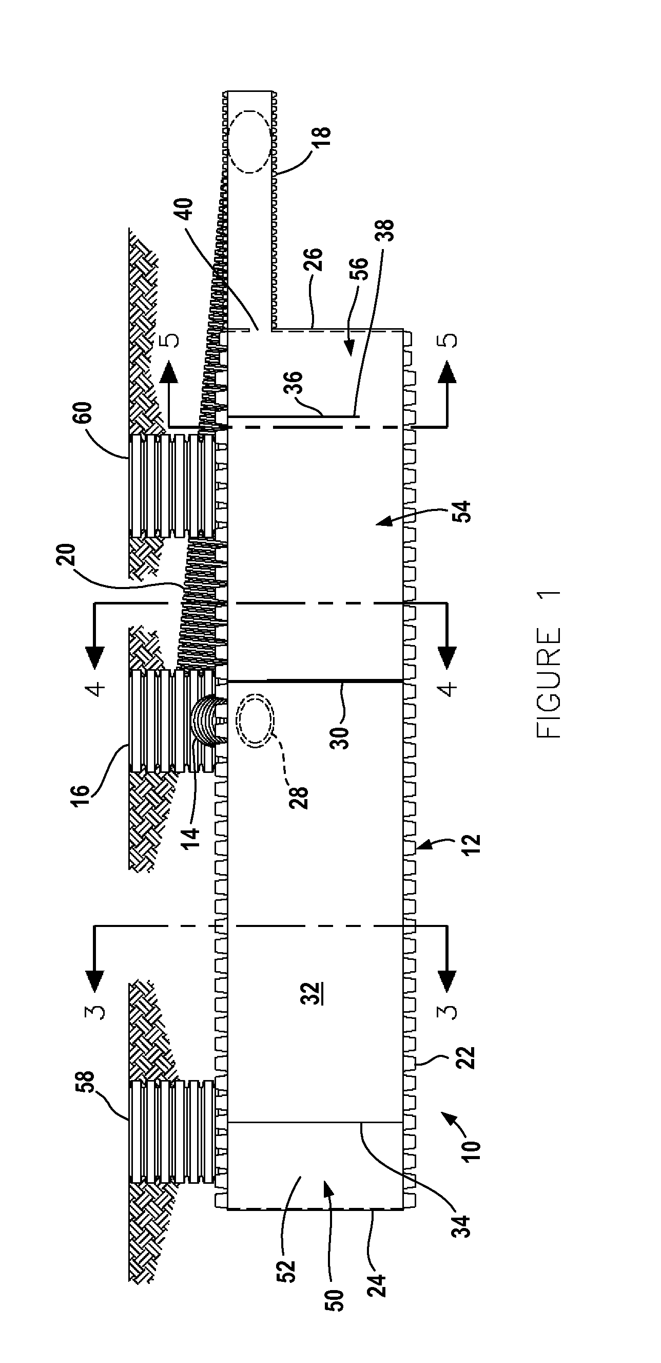
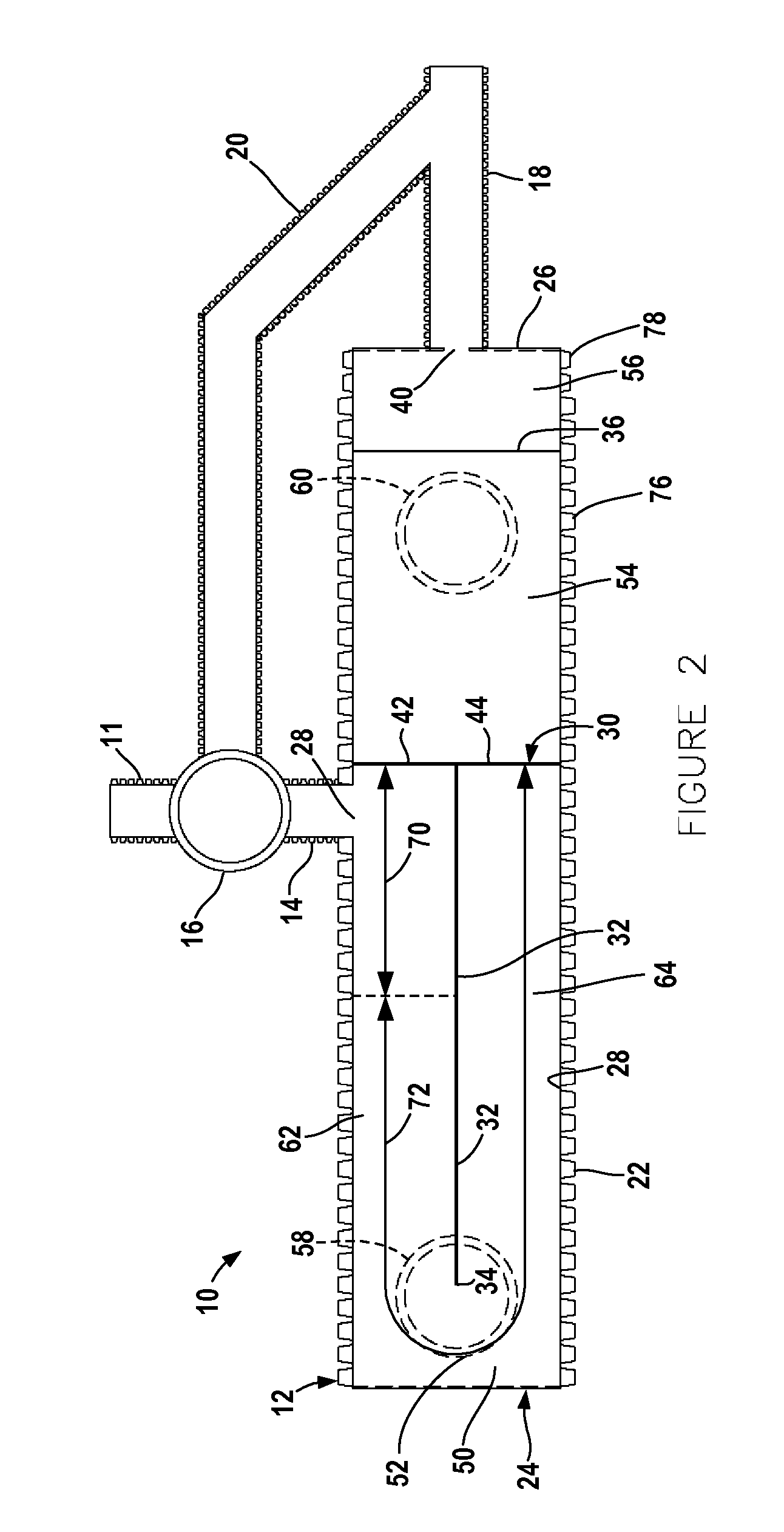
[0019]The figures illustrate a buried stormwater treatment system 10 including separator 12, stormwater inlet conduit 14, inlet conduit inspection and clean out riser 16, discharge conduit 18 and by-pass conduit 20 extending from riser 16 to conduit 18.

[0020]Separator 12 includes an elongate cylindrical body 22 having upstream bulkhead 24 closing the upstream end of the body, and downstream bulkhead 26 closing the downstream end of the body. Inlet conduit 14 opens into the interior of body 22 at inlet port 28 located in the central portion of the body, between bulkheads 24 and 26 and adjacent the top of the body as illustrated in FIGS. 1 and 4. Interior bulkhead 30 extends across the interior of body 22 between port 28 and bulkhead 26 a short distance from inlet port 28. A vertical divider wall 32 is joined to the top and bottom of the body 22 and to the bulkhead 30. The wall 32 extends from the bottom of the body 22 to the top of the body 22 and from interior bulkhead 30 to end 34 ...


PUM

PropertyMeasurementUnit
Fractionaaaaaaaaaa
Lengthaaaaaaaaaa
Widthaaaaaaaaaa

Abstract

A separator for stormwater includes a long, U-shaped sediment chamber and an oil chamber.

Description

FIELD OF THE INVENTION[0001]The invention relates generally to stormwater treatment, and particularly to a system and method for separating sediment and other pollutants from stormwater.BACKGROUND OF THE INVENTION[0002]Stormwater runoff is a major source of water pollution of lakes, rivers, and streams. Runoff from parking lots, construction sites, and agricultural areas contain sediment, oil, and other pollutants.[0003]Stormwater treatment systems have been developed to remove pollutants from stormwater runoff. In one system, stormwater flows into an inlet conduit connected to a buried water quality separator that removes pollutants from the stormwater. Stormwater flows into one end of the separator and flows longitudinally along the length of the separator through a sediment chamber and an oil chamber and out the other end of the separator.[0004]The known water quality separator includes an elongate tubular body that surrounds the sediment and oil chambers. The inlet conduit opens...

Claims


Application Information

Patent Timeline
IPC IPC(8): B01D21/02
CPCB01D21/003B01D21/02B01D2221/12E03F5/14
Inventor COLLINGS, PATRICK X.
Owner LANE ENTERPRISES
Why Eureka
Try Eureka