DC bus short circuit compliant power generation systems using induction machine

a power generation system and induction machine technology, applied in the direction of engine starters, electric generator control, dynamo-electric converter control, etc., can solve the problems of causing problems such as affecting the efficiency of the startup function, and causing significant increase in the installed electric power

Active Publication Date: 2008-12-02
HONEYWELL INT INC
View PDF16 Cites 9 Cited by
  • Summary
  • Abstract
  • Description
  • Claims
  • Application Information

AI Technical Summary

Benefits of technology

[0018]In one aspect of the present invention, a power generation system comprises an induction machine; a first induction machine winding; a second machine winding; an excitation bridge electrically connected to the second induction machine winding; a main rectifier electrically connected to the first induction machine winding; a diode electrically connecting the excitation bridge and the main rectifier, the diode being biased in reverse polarity during a short circuit; and a permanent magnet machine supplying AC power to a rectifier bridge, the rectifier bridge converting the AC power from the permanent magnet machine to deliver DC power to the excitation bridge, wherein a DC bus of the rectifier bridge does not collapse during a short circuit of the main rectifier.

Problems solved by technology

The overall result has been a significant increase in the installed electric power, creating challenges in accommodating this equipment in the new platforms.
An efficient startup function is typically challenging because of limited power availability.
Finally, short circuit current function is required when an external short circuit fault occurs at the DC distribution bus.
However, the rotor flux in a typical PMM is fixed and cannot be controlled or disengaged when a short circuit is initiated.
Therefore, the PMM presents a hazard in some applications, leading to its limited use, particularly in the aerospace industry.
However, supplying short circuit current to the DC bus when an external or internal fault occurs across the DC bus cannot be performed.
The reason is lack of a supply source required for the bridge to excite IM.

Method used


Image

  • DC bus short circuit compliant power generation systems using induction machine
  • DC bus short circuit compliant power generation systems using induction machine
  • DC bus short circuit compliant power generation systems using induction machine

Examples


Embodiment Construction

[0027]The following detailed description is of the best currently contemplated modes of carrying out the invention. The description is not to be taken in a limiting sense, but is made merely for the purpose of illustrating the general principles of the invention, since the scope of the invention is best defined by the appended claims.

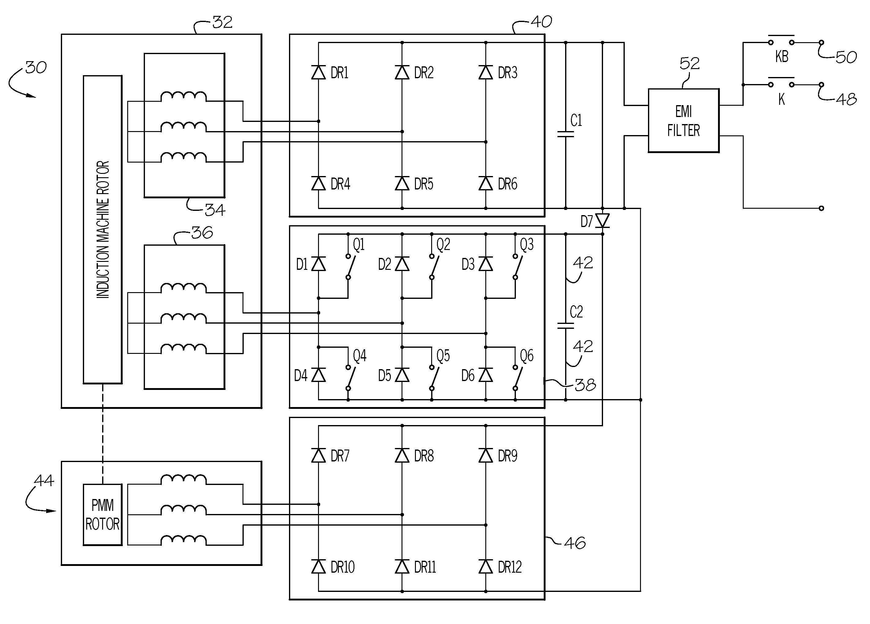
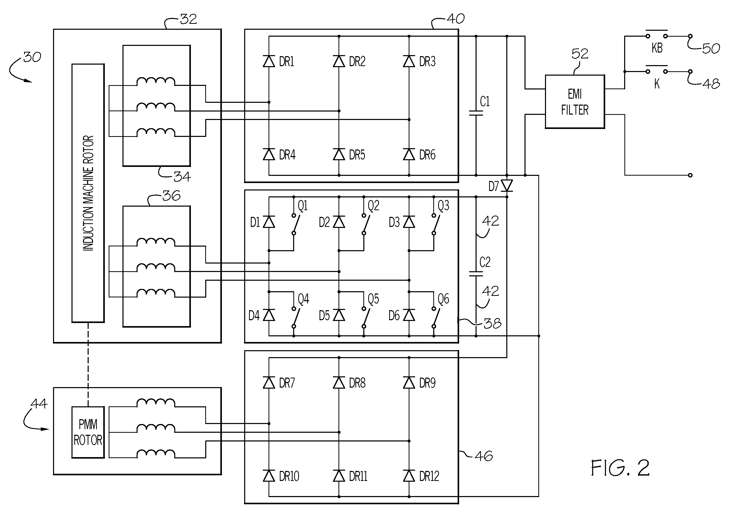
[0028]Briefly, the present invention provides an electric power generation system employing a solid state electronically controlled induction machine (IM) capable of self-start motoring, power generation, and distribution-system compatibility for fault interruption. The short circuit compliant power generation system of the present invention may have an internal bus that does not collapse when the main DC bus is shorted.

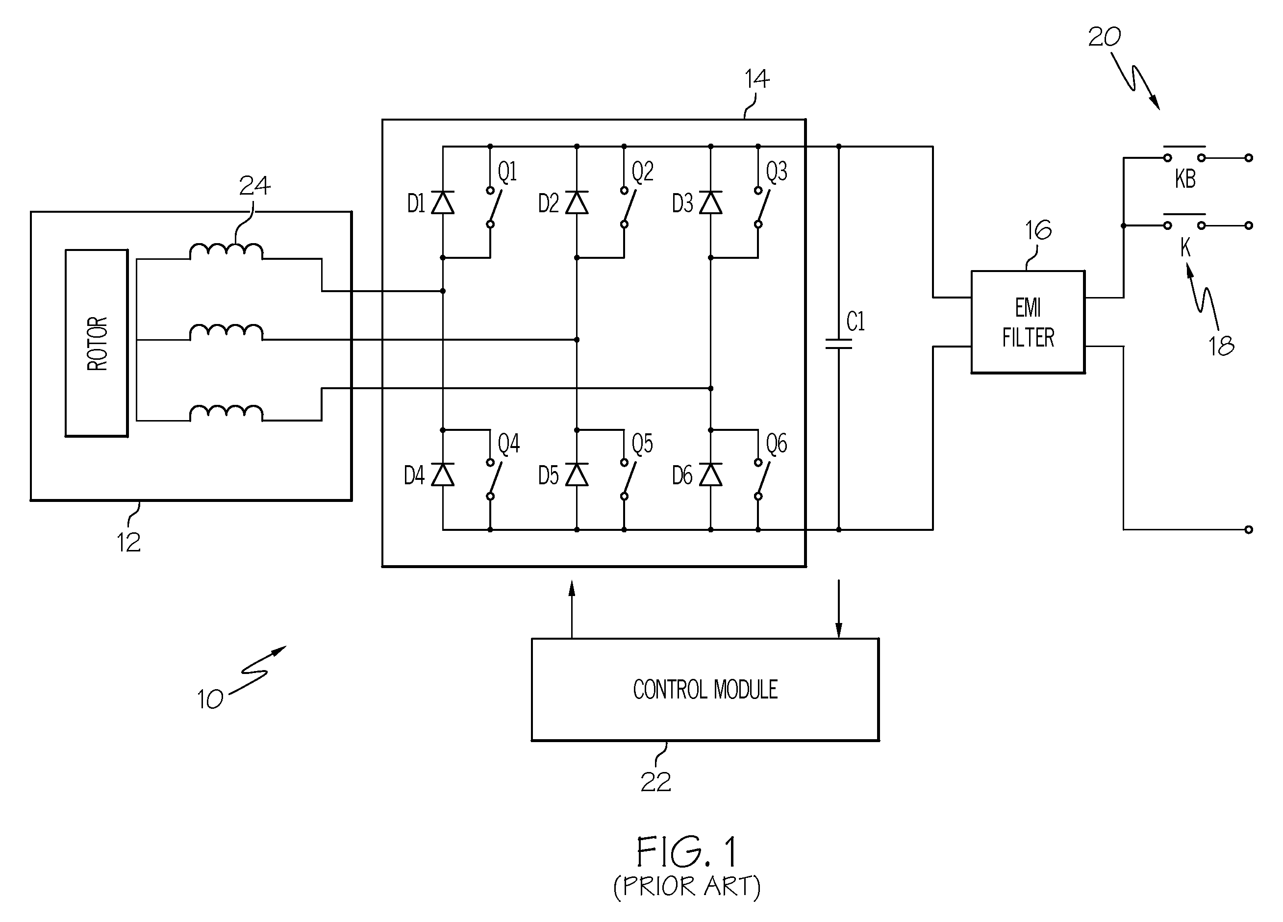
[0029]Conventional electric power generation systems employing a solid state electronically controlled IM may be capable of self-start motoring and power generation, but, when the DC bus voltage may collapse upon a failure, an additional...


PUM


Abstract

Conventional electric power generation system employ a solid state electronically controlled IM that may be capable of self-start motoring and power generation, but, when the DC bus voltage collapses upon a failure, an additional external source of DC voltage is not available for IM excitation. The present invention provides an internal bus that does not collapse when the main DC bus is shorted. This internal or auxiliary bus may be used to excite the IM to provide generation function. The power generation systems of the present invention may play a significant role in the modern aerospace and military industries.

Description

BACKGROUND OF THE INVENTION[0001]The present invention generally relates to a DC bus short circuit compliant power generation system, and more particularly, to a DC bus short circuit compliant power generation system having an internal bus that does not collapse when the main DC bus is shorted.[0002]Power generation systems (PGS) play a significant role in the modern aerospace / military industry. Recently, this has been particularly true in the area of more electric architecture (MEA) for aircraft and spacecraft. The commercial aircraft business is moving toward a no-bleed air environmental control system (ECS), variable frequency (VF) power distribution systems, and electrical actuation. The next-generation Boeing airplane (the Boeing 787 platform) and the Airbus airplane will most likely use MEA. Some military aircraft already utilize MEA for primary and secondary flight control among other functions.[0003]These new aerospace trends have significantly increased power generation nee...

Claims


Application Information

Patent Timeline
Patent Type & Authority Patents(United States)
IPC IPC(8): F02N11/04
CPCH02M7/493H02P1/00
Inventor GANEV, EVGENIFIZER, LEROY A.
Owner HONEYWELL INT INC
Why Eureka
Try Eureka