Energy management system and method to monitor and control multiple sub-loads

a management system and energy management technology, applied in non-electric variable control, process and machine control, instruments, etc., can solve the problems of no enabling description of the technology employed to manage energy consumption on either web-site, reliable control products do not address non-commercial applications, and the cost, complexity and physical footprint are reduced. , the effect of simple energy management algorithm

Active Publication Date: 2008-12-02
GRIDPOINT
View PDF56 Cites 136 Cited by
  • Summary
  • Abstract
  • Description
  • Claims
  • Application Information

AI Technical Summary

Benefits of technology

[0043]As illustrated in FIG. 8, the present invention takes advantage of the fact that the power supply for the multiple electrical loads normally comes through a few common power distribution panels 212 (such as circuit breaker panels). In the present invention, the many single-circuit power monitoring devices (traditional approach) are replaced with a few, or just one, multiple-circuit power monitoring device(s) 212 which can significantly reduce the cost, complexity, and physical footprint for the power monitoring component of the energy management system. To this point, most of the energy management systems in use today do not include basic power monitoring due to the cost, complexity, and physical footprint associated with installing multiple single-circuit power monitoring devices (considered too expense to install). As a result, traditional energy management systems cannot make optimal automatic and dynamic control decisions because they do not have real-time power usage data available—resulting in simplistic energy management algorithms that do not realize a significant portion of the

Problems solved by technology

There is no on-board or downloadable capability for software/firmware power management or for direct device-to-device communication.
However, there is no enabling description of the technology employed to manage energy consumption provided on either web-site.
The Reliable Controls products do not address non-commercial applications.
The above referenced Web pages primarily describe individual control devices and do not offer any type of integrated power monitoring and control device.
None provide an interfaced

Method used


Image

  • Energy management system and method to monitor and control multiple sub-loads
  • Energy management system and method to monitor and control multiple sub-loads
  • Energy management system and method to monitor and control multiple sub-loads

Examples


Embodiment Construction

[0066]In the following discussions for purposes of clarity with respect to explaining the current invention, common components are numbered according to their first appearance in a drawing and well-known components are to be interpreted according to the understanding of a person ordinarily skilled in the art, e.g., wide area network (WAN) and Bluetooth are well-known in the art and are not described but given their well-known meanings.

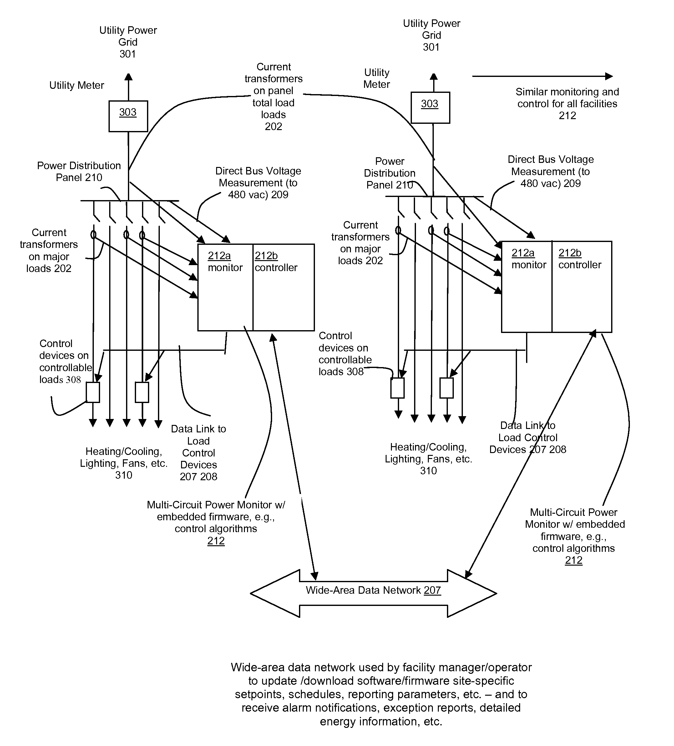
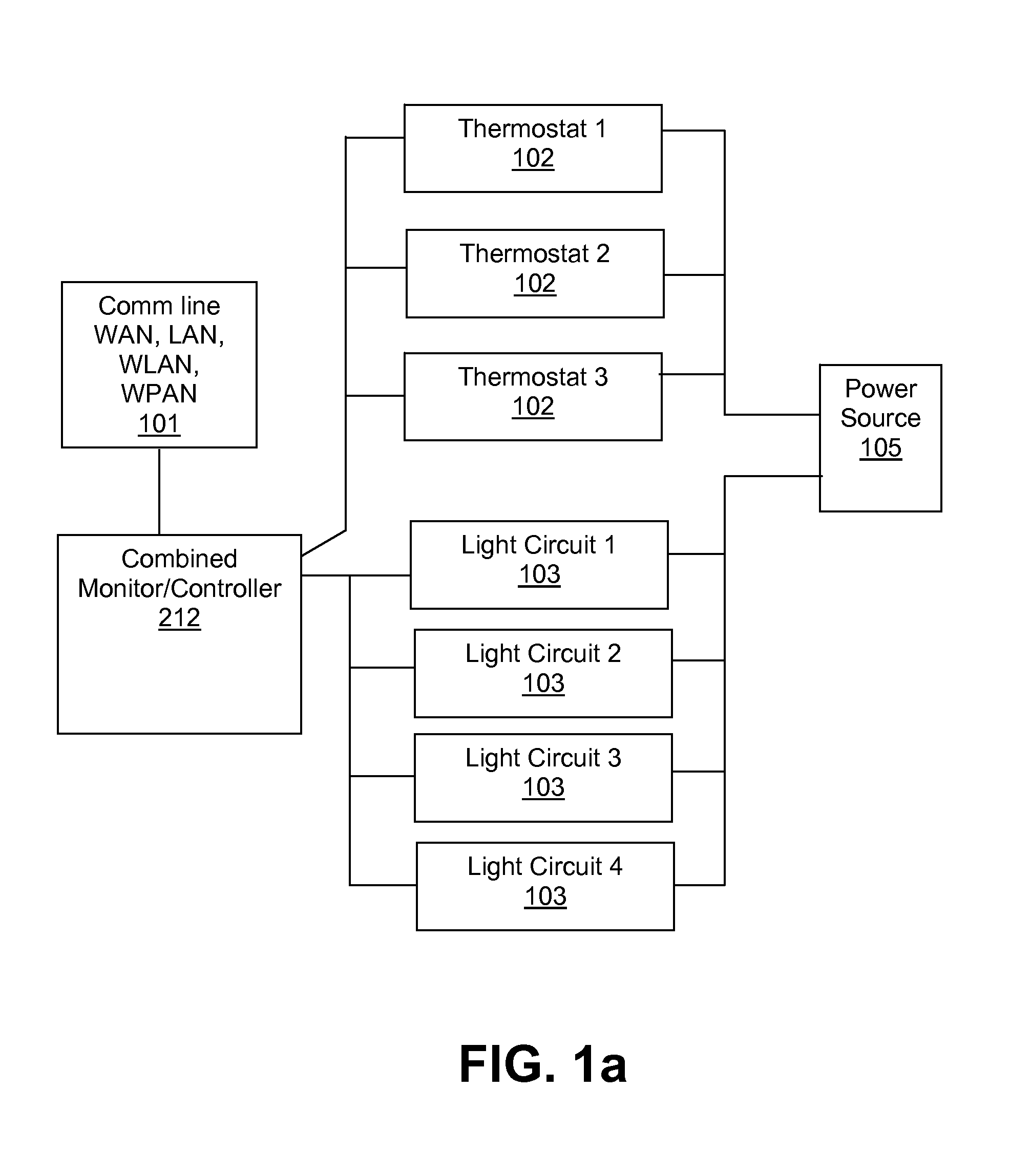
[0067]Referring now to FIGS. 2 and 5, a system with embedded control algorithms, according to a preferred embodiment of the present invention, monitors and controls multiple electrical loads of various configurations 510511515516—including both single 204 and poly-phase applications 203. The single monitor / controller 212 is simply wired 209 to common voltages at an electrical distribution panel 210 and can be connected to remote current sensing units 515 to accept power variable measurements. In a preferred embodiment, the monitor / controller 212 of the...


PUM


Abstract

A power management device, including: a monitor module that directly monitors energy usage of at least one energy load to generate at least one measurement of energy usage by the at least one energy load; and a control module operatively coupled to the monitor module to control energy usage by the at least one energy load in a pre-determined manner that is based on the at least one measurement of energy usage, wherein the control module controls the at least one energy load via a data link.

Description

CROSS-REFERENCE TO RELATED APPLICATIONS[0001]This claims the benefit of U.S. Provisional patent application Ser. No. 60 / 570,890, filed May 14, 2004 and U.S. Provisional patent application Ser. No. 60 / 573,382, filed May 24, 2004, both incorporated herein by reference in their entirety.REFERENCE TO COMPUTER PROGRAM LISTING APPENDIX[0002]A computer program listing appendix is concurrently submitted with this specification on a CD-R disc, the disc contains the file APV31694b.code.txt, having this appendix in ASCII format, having a file size of 167 KB (171,035 bytes), created May 13, 2005; the material on the compact disc is incorporated herein by reference in its entirety.BACKGROUND OF THE INVENTION[0003]1. Field of the Invention[0004]The present invention relates to an energy management system and method for monitoring and controlling multiple sub-loads. In particular, the present invention comprises an integrated combination monitor / controller that simultaneously monitors a plurality ...

Claims


Application Information

Patent Timeline
IPC IPC(8): G06F19/00
CPCG01D4/002H02J13/0062G01R22/063Y02B90/241Y04S20/32Y04S40/124Y02B90/248Y02B90/245Y04S20/40Y04S20/52Y02E60/7838H02J13/00016Y02B90/20Y02E60/00Y04S20/30
Inventor HOWELL, DONALD W.VINSON, MARK W.BLEVINS, FRANK O.TAMAGNI, JR., ARMAND J.CAMPBELL, MICHAEL L.
Owner GRIDPOINT
Why Eureka
Try Eureka