Solenoid device for engaging power takeoffs

a solenoid and power takeoff technology, applied in the direction of belt/chain/gearing, mechanical equipment, belt control, etc., can solve the problems of considerable use of energy, and overheating of the solenoid

Active Publication Date: 2008-12-09
O M F B S P A HYDRAULIC COMPONENTS
View PDF14 Cites 12 Cited by
  • Summary
  • Abstract
  • Description
  • Claims
  • Application Information

AI Technical Summary

Benefits of technology

[0026]An object of the present invention is to provide an engaging device for power takeoffs actuated by a solenoid which enables one to overcome the aforesaid limitations and drawbacks with respect to the engaging devices of this type.

Problems solved by technology

The solenoid is constituted by a large single coil driven with a high current and hence with considerable use of energy and consequent overheating of the solenoid.
The solenoids are constituted by a large single coil driven with a high current and hence with considerable use of energy and consequent overheating of the solenoids.
A problem with all the above mentioned engaging devices is evident in the engaging phase, which is better described below and which can be called “tooth against tooth jamming”.
In all the above mentioned devices, in fact, such jamming leads to the unsuccessful completion of the engaging phase and then to the necessary repetition of this phase by the operator.
This leads, above other things, to a partial damaging of the gear teeth for every unsuccessful attempt and then, over a long period, to a failure of the power takeoff.
Another problem of the prior art devices is that, in order to furnish information on the real engaging state of the takeoff (which is basic for the takeoff interface towards the electronic units for the control of the vehicle automatic gear), it is necessary to use and install on the takeoff an end-stroke sensor, called “engagement signaler”.
Therefore, possible oil leakage points are introduced, with the consequence of a possible breakdown of the gears on which the takeoff is installed.
Possible malfunctions of said engagement signaler can also lead to wrong information to the gears electronic control unit, and therefore to damaging actions on said gears.
A further problem with the prior art devices is the impossibility of furnishing information about the temperature of the gear on which the power takeoff is mounted.
Light vehicle gears are not provided with a system for controlling the temperature and, in case they work with lack of internal lubricant, they quickly get damaged.

Method used


Image

  • Solenoid device for engaging power takeoffs
  • Solenoid device for engaging power takeoffs
  • Solenoid device for engaging power takeoffs

Examples


Embodiment Construction

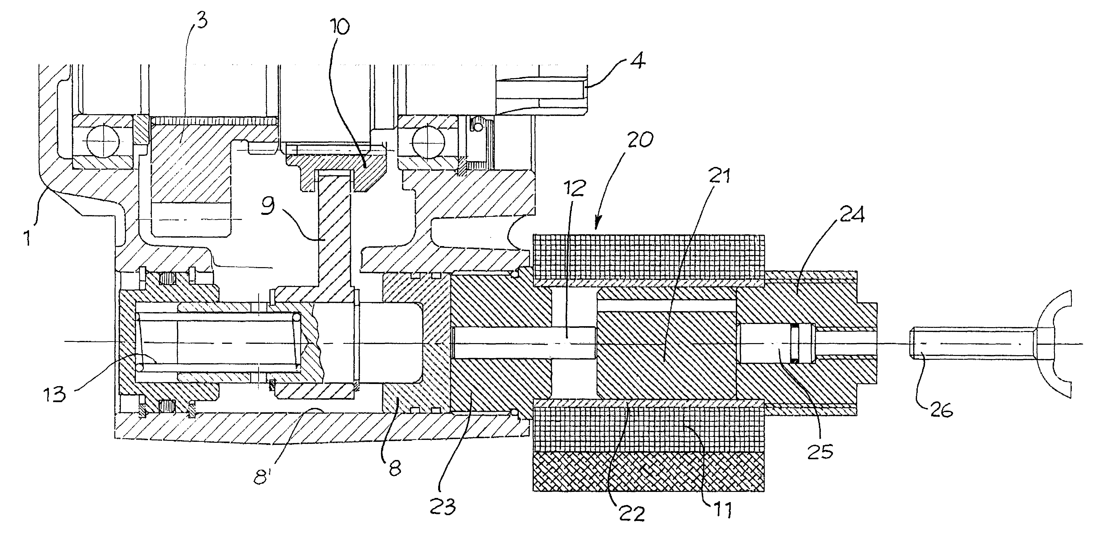
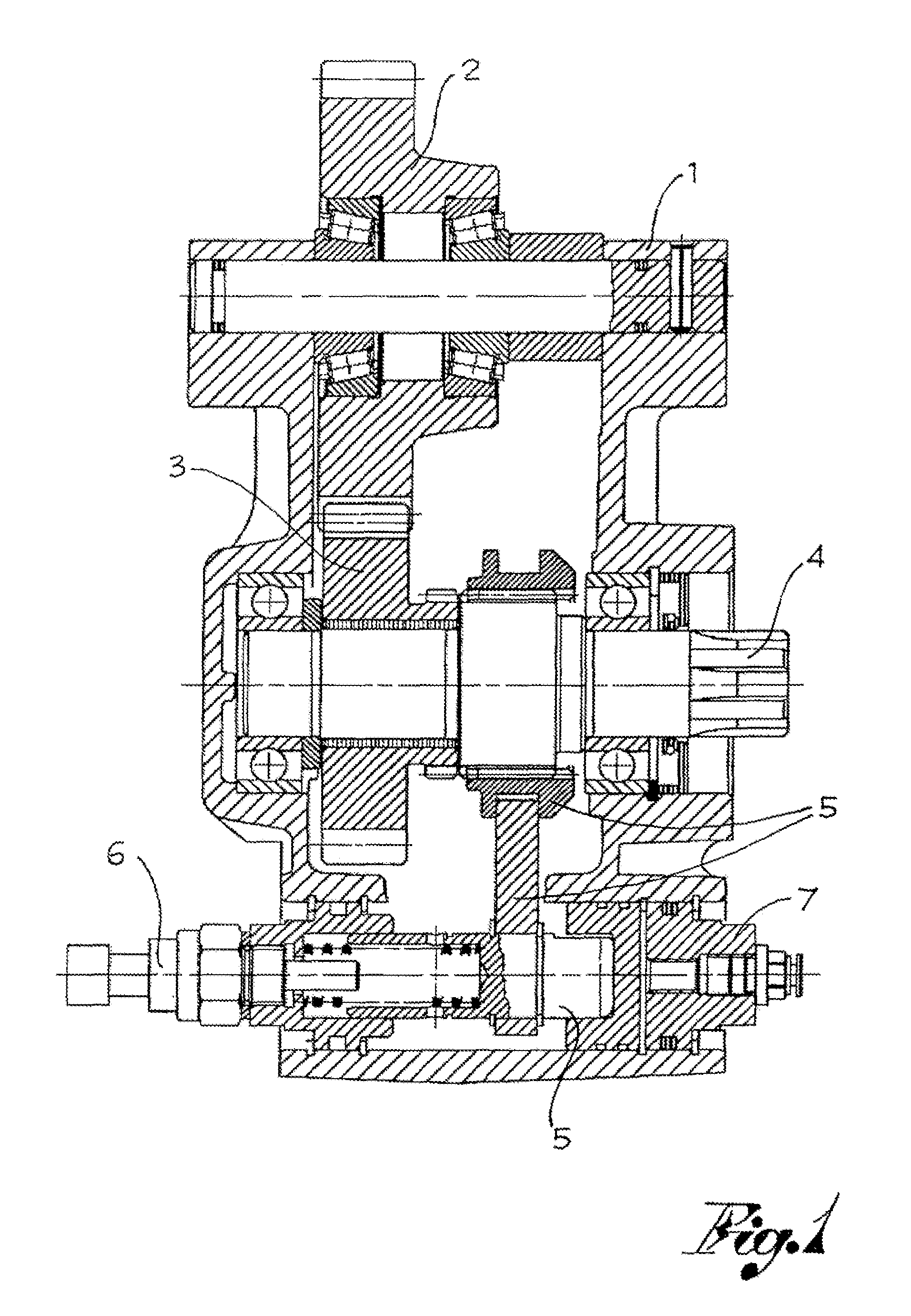
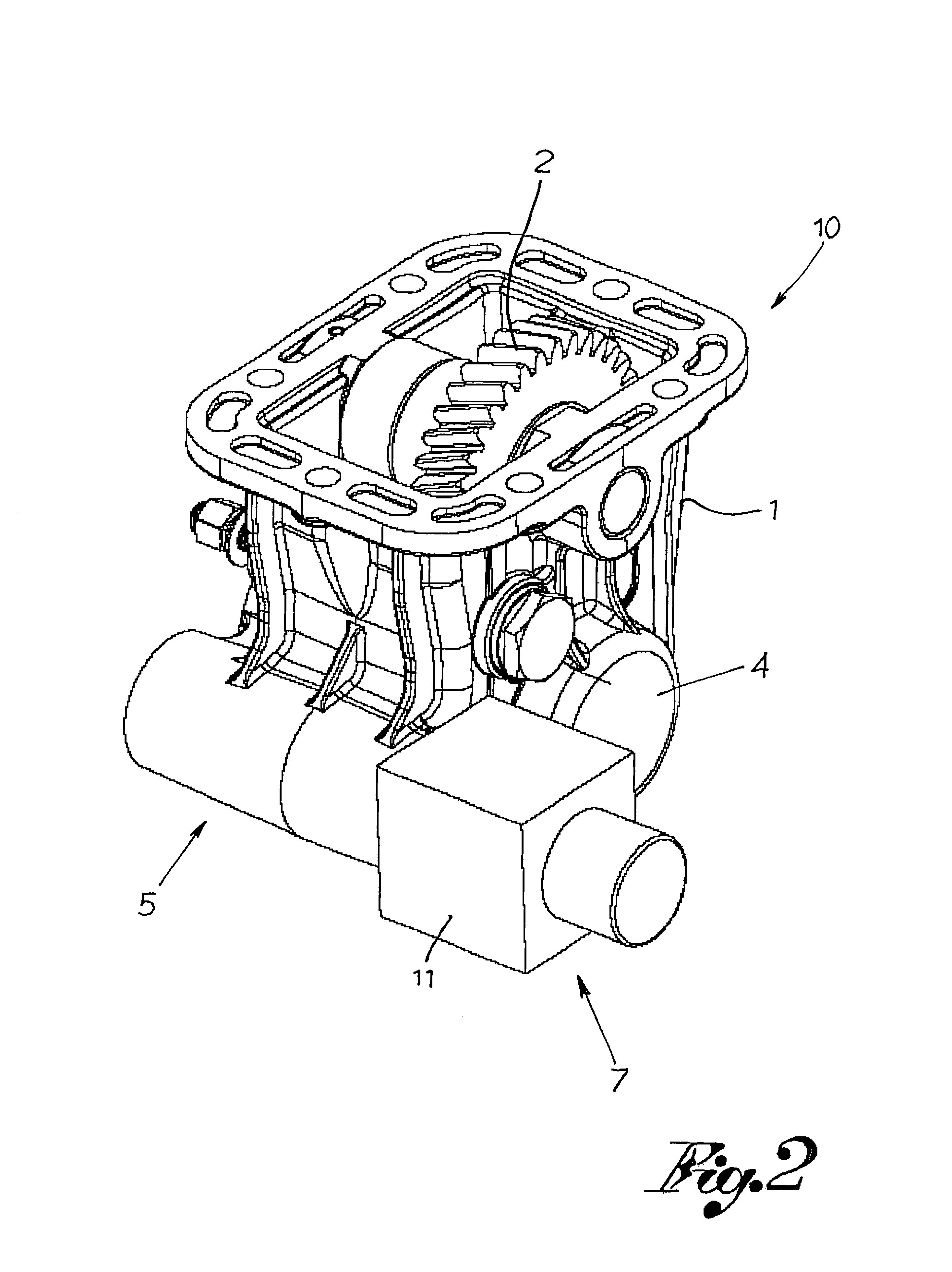
[0038]With reference to FIGS. 2-6, the number 10 globally designates a power takeoff for industrial vehicles, comprising:

[0039]a main body or box 1 (usually made of cast iron or aluminium) which constitutes the outer container of all the other mechanical elements and serves as fixed connection to the transmission gear;

[0040]a main gear 2 which is engaged with the gear inside the transmission gearbox and which transfers motion from the transmission gear to other gears inside the power takeoff; one or more driven or auxiliary gears 3 of the power takeoff, which are engaged with the main gear 2;

[0041]an output shaft 4 adapted to transmit motion from the internal gears 2,3 of the power takeoff to an external device (usually a pump);

[0042]an engaging assembly 5 which allows the transfer of motion and hence of power only when it is moved to an active position, called engaged power takeoff position; and

[0043]actuating means 7 to move said engaging assembly 5 from an inactive position to sa...


PUM


Abstract

A device for engaging power takeoffs, primarily used to drive a load from the engine of a vehicle, has an electromagnet with a single winding of small size which is driven by a microprocessor system in PWM mode allowing to differentiate the current intensity of the engaging phase and of the phase of maintaining said engaging. The control system monitors, without the aid of external sensors, parameters such as electromagnet current, power supply and electromagnet voltage, electromagnet winding resistance, electromagnet winding inductance. From these parameters, the system is able to determine the engaging or unengaging position of the power takeoff, and it is able automatically to uncouple if the monitored parameters do not fall within the expected ranges, simultaneously notifying the user of the protective intervention.

Description

[0001]This application is a continuation-in-part of International Application No. PCT / IT2005 / 000727, filed on Dec. 9, 2005.BACKGROUND OF THE INVENTION[0002]The present invention relates to power takeoffs for industrial vehicles and in particular it refers to a device for engaging such power takeoffs, able to be actuated electrically by means of a solenoid.[0003]As is well known, the power takeoff is a mechanical device with gears, connectable to the transmission of industrial vehicles and suitable for transmitting power from the gear to an external use, in particular to a rotary hydraulic pump which transforms mechanical power into hydraulic power to be supplied to a hydraulic system for multiple applications.[0004]FIG. 1 shows an example of a power takeoff according to the state of the art.[0005]The power takeoff is mainly constituted by:[0006]a main body or box 1 (usually made of cast iron or aluminium) which constitutes the outer container of all the other mechanical elements and...

Claims


Application Information

Patent Timeline
Patent Type & Authority Patents(United States)
IPC IPC(8): F16H59/00B60K17/04
CPCB60K17/28F16D48/06F16H59/68F16H63/304F16D27/118Y10T477/647F16D2027/002F16D2500/1022F16D2500/10437F16D2500/10462F16D2500/3022F16D2500/3028F16D2500/30401F16D2500/30405F16D2500/31413F16D2500/31473F16D2500/70418F16H2063/305Y10T477/6389Y10T74/2003Y10T74/19251
Inventor BIANCHI, AMEDEO
Owner O M F B S P A HYDRAULIC COMPONENTS
Why Eureka
Try Eureka