
EGR Cooling System with Multiple EGR Coolers

a cooling system and cooler technology, applied in the direction of mechanical equipment, machines/engines, non-fuel substance addition to fuel, etc., can solve the problems of large egr cooling demands of diesel engines, adversely affecting engine operation, and increasing intake temperatures, so as to avoid egr fouling, increase heat transfer surface area, and ensure the effect of cooling

Active Publication Date: 2008-12-09
FORD GLOBAL TECH LLC
View PDF21 Cites 57 Cited by
  • Summary
  • Abstract
  • Description
  • Claims
  • Application Information

AI Technical Summary

Benefits of technology

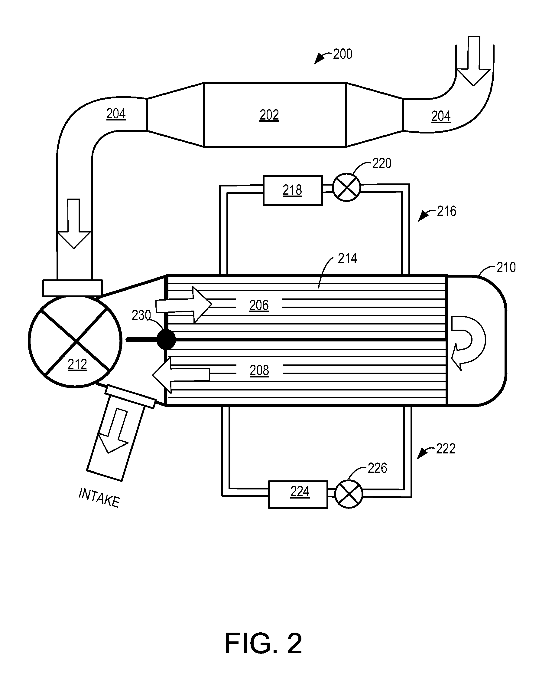
[0003]To at least partially address the issue of providing adequate cooling to engines while avoiding EGR fouling, an EGR cooling system is provided. The EGR cooling system comprising a plurality of EGR coolers configured to cool the EGR to a plurality of successively lower temperatures, where at least one of the plurality of EGR coolers includes a finned EGR cooler that comprises a plurality of channels for dissipating heat in the EGR, the plurality of channels increasing heat transfer surface area while having sufficient fin spacing to avoid clogging. The EGR cooling system may further comprise a catalyst configured to remove particle matters and / or hydrocarbons from the EGR, the catalyst positioned upstream of at least one of the plurality of EGR coolers.
[0004]In this way, the engine may provide high levels of EGR cooling, while addressing issues of EGR fouling and engine packaging. Specifically, by providing a plurality of EGR coolers that cool the EGR to successively lower temperatures, it may be possible to meet the EGR cooling demand of a high load engine without drastically increasing the size of the EGR cooling system. Further, by positioning a catalyst upstream of at least one of the plurality of EGR coolers, it may be possible to reduce EGR fouling. Likewise, by using an EGR cooler with appropriate fin spacing, it may be possible to increase heat transfer surface area within the EGR cooler package space and further increase heat dissipation to the coolant but avoid clogging due to hydrocarbon deposit build up.

Problems solved by technology

Without cooling, EGR may increase intake temperatures above a level that adversely affects engine operation.
Some diesel engines may have large EGR cooling demands due to the large amounts of EGR needed to meet NOx emissions.
In such engines, using the engine coolant alone to cool the EGR may either be inadequate or require an excessively large EGR cooler that exceeds available package space in an engine compartment.
However, one issue with the above solution is potential fouling inside the lower temperature EGR cooler when more hydrocarbons and vapor are deposited or condensed when the EGR is cooled to a lower temperature by the additional EGR cooler.

Method used


Image

  • EGR Cooling System with Multiple EGR Coolers
  • EGR Cooling System with Multiple EGR Coolers
  • EGR Cooling System with Multiple EGR Coolers

Examples


Embodiment Construction

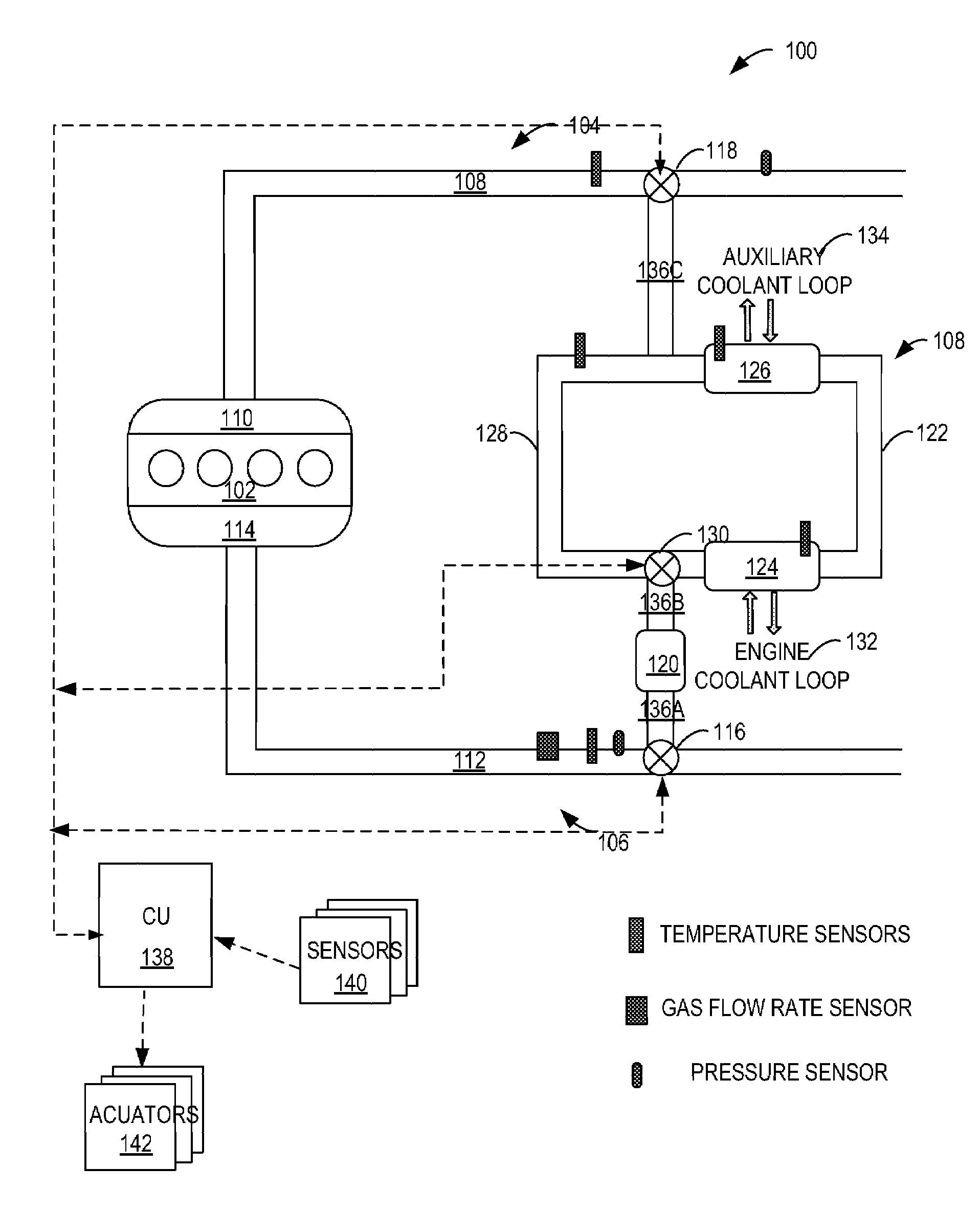
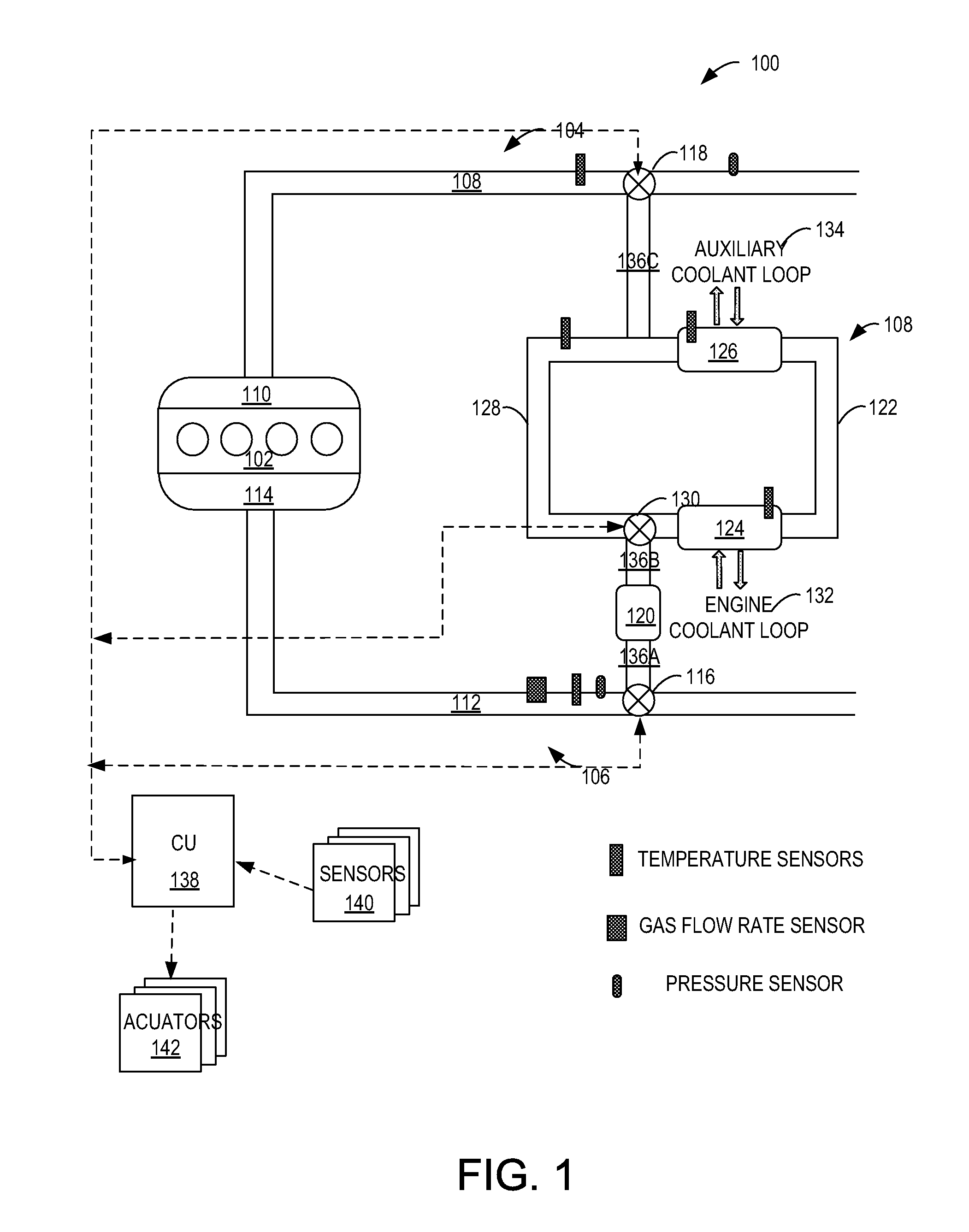
[0008]FIG. 1 illustrates an example EGR cooling system 100 configured to address EGR cooling demand of an engine that can operate in a wide range of engine loads, such as a turbocharged diesel engine, and in the meantime reduce EGR fouling.

[0009]The system 100 may include an engine 102 coupled to an intake system 104 and an exhaust system 106. The engine 102 may be of various internal combustion engine types, such as a diesel burning engine, a gasoline burning engine, an alternative fuel, such as bio-diesel and ethanol, burning engine, or combinations thereof.

[0010]The intake system 104 may include an intake passage 108 coupled to an intake manifold 110, which is in turn coupled to the engine 102. The exhaust system 106 may include an exhaust passage 112 coupled to an exhaust manifold 114, which is in turn coupled to the engine 102.

[0011]The EGR cooling system 100 may include an EGR valve 116 for diverting exhaust in the exhaust passage 112 as EGR, and an EGR mixer 118 for mixing th...


PUM


Abstract

An EGR cooling system is provided. The EGR cooling system comprising a plurality of EGR coolers configured to cool the EGR to a plurality of successively lower temperatures, where at least one of the plurality of EGR coolers includes a finned EGR cooler that comprises a plurality of channels for dissipating heat in the EGR, the plurality of channels increasing heat transfer surface area while having sufficient fin spacing to avoid clogging. The EGR cooling system may further comprise a catalyst configured to remove particle matters and / or hydrocarbons from the EGR, the catalyst positioned upstream of at least one of the plurality of EGR coolers.

Description

BACKGROUND AND SUMMARY[0001]Exhaust gas recirculation (EGR) is commonly used for NOx emission control in an internal combustion engine. Without cooling, EGR may increase intake temperatures above a level that adversely affects engine operation. As a way of dealing with this issue, EGR coolers using engine coolant as a low temperature media have been used to cool EGR gas temperatures.[0002]Some diesel engines may have large EGR cooling demands due to the large amounts of EGR needed to meet NOx emissions. In such engines, using the engine coolant alone to cool the EGR may either be inadequate or require an excessively large EGR cooler that exceeds available package space in an engine compartment. As an alternative, a standard-sized EGR cooler may be followed by an additional EGR cooler that uses a lower temperature coolant to further cool the EGR. However, one issue with the above solution is potential fouling inside the lower temperature EGR cooler when more hydrocarbons and vapor ar...

Claims


Application Information

Patent Timeline
Patent Type & Authority Patents(United States)
IPC IPC(8): F02B47/08F02B47/10
CPCF02M25/0722F02M25/0728F02M25/0732F02M25/0737F02M25/074F02M25/0754Y02T10/121F02M26/19F02M26/25F02M26/24F02M26/32F02M26/35F02M26/47
Inventor STYLES, DANIEL JOSEPHHOARD, JOHN WILLIAMGIULIANO, JULIAMEYER, ROBERT HORNBLOWER
Owner FORD GLOBAL TECH LLC
Learn More