
Compact light weight autothermal reformer assembly

a technology of autothermal fuel and reformer, which is applied in the direction of gas-gas reaction process, separation process, physical/chemical process catalyst, etc., can solve the problem of more difficult reform of fuel to be processed, achieve faster start-up of reformer, improve fuel conversion rate, and reduce the ignition temperature of fuel gas fraction

Inactive Publication Date: 2005-11-29
HYAXIOM INC
View PDF7 Cites 4 Cited by
  • Summary
  • Abstract
  • Description
  • Claims
  • Application Information

AI Technical Summary

Benefits of technology

This patent describes a fuel cell system that uses a foam-based catalyst support with enhanced heat transfer and gas mixing capabilities. The foam support has a high surface area and is coated with a porous layer of catalyst. The system includes a cylindrical reactor with multiple chambers for fuel gas, steam, and air. The foam support provides a more efficient heat transfer path and allows for faster start-up and reduced size and weight of the reformer. The system also uses a small amount of air to promote autothermal reforming and can be rapidly heated with a minimum energy input. The foam support bed is formed from a monolith with interconnected open cells, which increases the catalyzed surface area and reduces the volume and weight of the bed. The system is compact and lightweight, making it ideal for vehicular applications.

Problems solved by technology

Autothermal reformers are often used when higher operation temperatures are required for the reforming process because the fuel to be processed is more difficult to reform.

Method used


Image

  • Compact light weight autothermal reformer assembly
  • Compact light weight autothermal reformer assembly
  • Compact light weight autothermal reformer assembly

Examples


Embodiment Construction

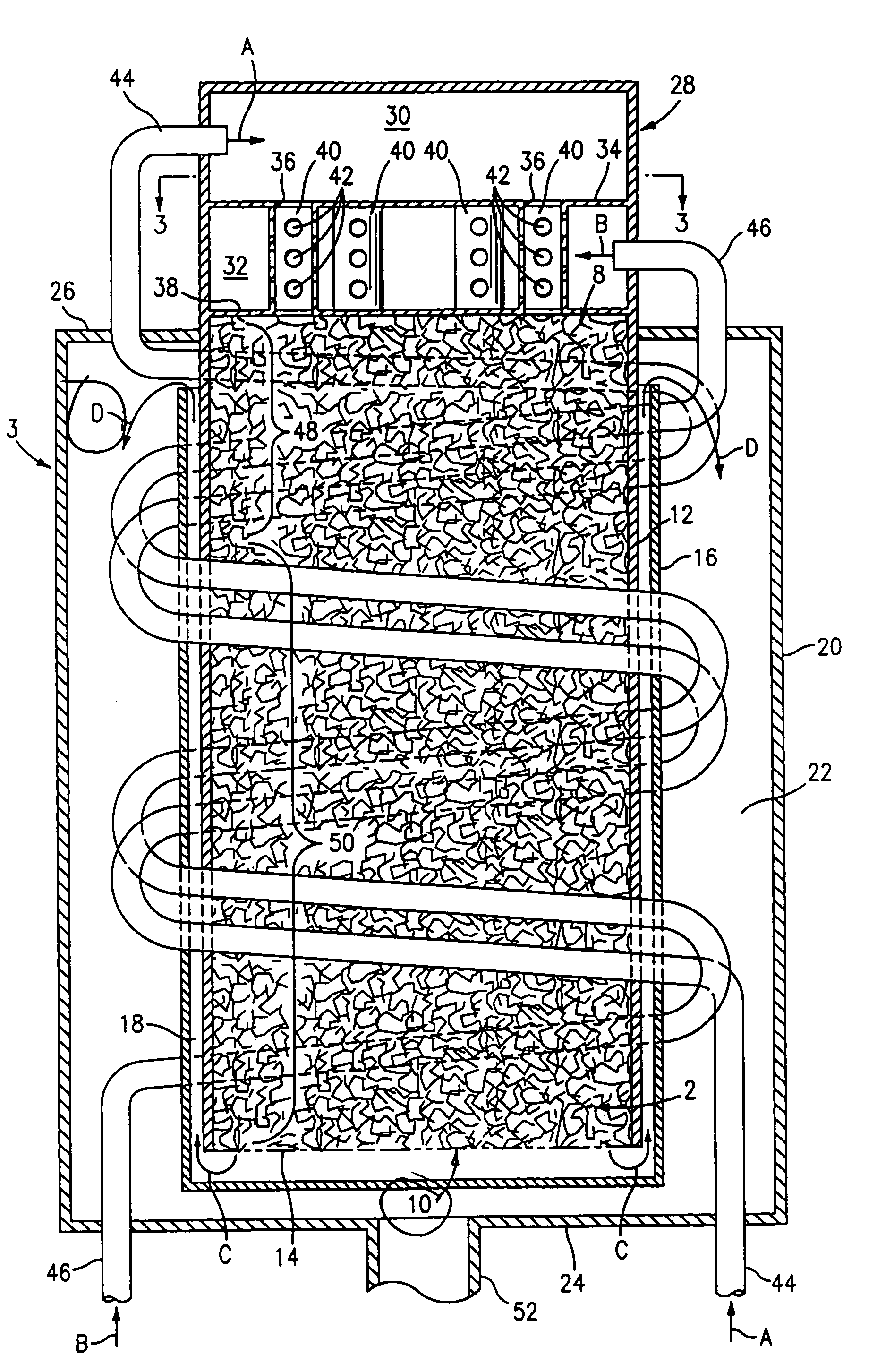
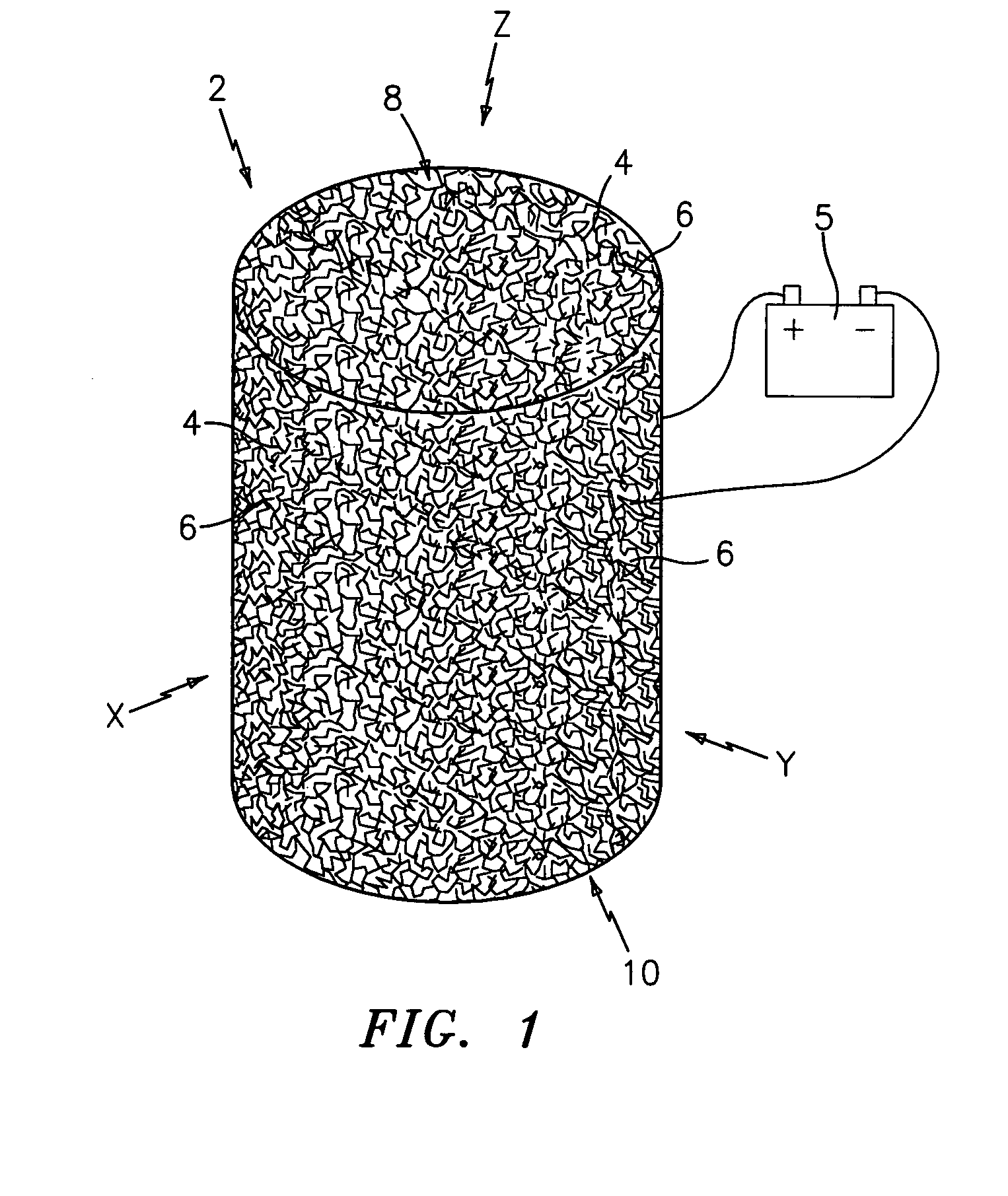
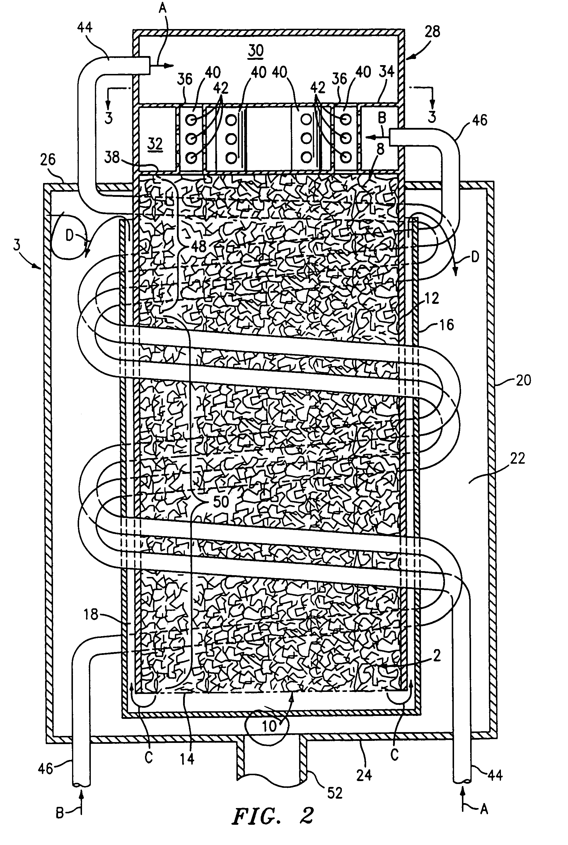
[0027]Referring now to the drawings, there is shown in FIG. 1 a perspective view of a cylindrical form of a catalyst bed formed in accordance with this invention, which bed is denoted generally by the numeral 2. The catalyst bed 2 is a monolithic open cell foam component which includes a lattice network of tendrils 4 which form a network of open cells 6 which are interconnected in the X, Y and Z directions within the bed 2. It will be appreciated that the catalyst bed 2 can be formed from a single monolith or from a plurality of thinner monoliths stacked one atop the other. The latter approach could simplify the differential catalyzation of the bed 2, and could also reduce thermal stresses imparted to the bed 2 during operation of the reformer. The interconnected open cells 6 are operable to form an enhanced fuel gas mixing and distribution flow path from end 8 to end 10 of the bed 2. The open cells 6 and the tendrils 4 also provide a very large catalyzable surface area in the bed 2...


PUM

PropertyMeasurementUnit
temperatureaaaaaaaaaa
temperaturesaaaaaaaaaa

Abstract

A fuel gas-steam reformer assembly, preferably an autothermal reformer assembly, for use in a fuel cell power plant, includes a catalyst bed which is formed from a cylindrical monolithic open cell foam body. The foam body is preferably formed from a high temperature material such as stainless steel, nickel alloys and iron-aluminum alloys, or from a ceramic material. The foam body includes open cells or pores which are contained within the metal or ceramic lattice. The lattice is coated with a porous wash coat which serves as a high surface area substrate onto which catalysts used in the reformer are applied. The foam body has an inlet end into which a mixture of fuel, steam and air is fed to begin the reforming process. An inlet portion of the foam body may be provided with an iron oxide and / or noble metal catalyst and the remainder of the foam body may be provided with a nickel and / or noble metal catalyst. An advantage of including an autothermal reformer in a fuel processing system is the compactness of the autothermal reformer. The inclusion of the foam catalyst bed rather than the traditional catalyzed pellet bed allows the reformer to be made even more compact and light weight.

Description

[0001]This is a continuation of a application Ser. No. 09 / 321,390, filed 27 May 1999, now U.S. Pat. No. 6,797,244.TECHNICAL FIELD[0002]This invention relates to a fuel gas steam reformer assembly. More particularly, this invention relates to an autothermal fuel gas steam reformer assembly which employs an open cell foam catalyst bed that reduces the size and weight of the reformer assembly.BACKGROUND ART[0003]Fuel cell power plants include fuel gas steam reformers which are operable to catalytically convert a fuel gas, such as natural gas or heavier hydrocarbons, into the primary constituents of hydrogen and carbon dioxide. The conversion involves passing a mixture of the fuel gas and steam through a catalytic bed which is heated to a reforming temperature which varies depending upon the fuel being reformed. Catalysts typically used are nickel catalysts which are deposited on alumina pellets. There are three types of reformers most commonly used for providing a hydrogen-rich gas str...

Claims


Application Information

Patent Timeline
Patent Type & Authority Patents(United States)
IPC IPC(8): B01J12/00B01J15/00B01J19/24B01J23/58B01J23/755B01J35/00B01J35/04C01B3/32C01B3/38C01B3/40H01M8/04H01M8/06
CPCH01M8/0631B01J12/007B01J15/005B01J19/2485B01J23/58B01J23/755B01J35/0006B01J35/04C01B3/382C01B3/40C01B2203/066C01B2203/0844C01B2203/085C01B2203/0883C01B2203/1011C01B2203/1017C01B2203/1023C01B2203/1029C01B2203/1041C01B2203/1047C01B2203/1052C01B2203/1064C01B2203/1076C01B2203/1082C01B2203/1094C01B2203/1235C01B2203/1276C01B2203/142C01B2203/1604C01B2203/82Y02E60/50B01J2208/025B01J2219/00081B01J2219/00094C01B2203/0244C01B2203/0283Y10S165/395Y10S165/397Y10S165/396Y02P20/52B01J35/19B01J35/56
Inventor LESIEUR, ROGER R.
Owner HYAXIOM INC
Learn More