Sealed rechargeable battery and battery module

a rechargeable battery and battery module technology, applied in the direction of cell components, final product manufacturing, sustainable manufacturing/processing, etc., can solve the problems of lowering battery performance, increasing component cost and fabrication cost, and poor so as to achieve high volume efficiency per battery output and increase lifetime and output.

Active Publication Date: 2008-07-01
PANASONIC CORP +1
View PDF6 Cites 5 Cited by
  • Summary
  • Abstract
  • Description
  • Claims
  • Application Information

AI Technical Summary

Benefits of technology

[0011]In light of the above conventional problems, the present invention has an object of providing a sealed rechargeable

Problems solved by technology

What is worse, since the number of components and the number of assembly steps are both increased, the component cost and the fabrication cost are increased.
Moreover, since the case 55 has a circular cross section, the cooling performance for the central portion of the battery is low, resulting in poor volume efficiency per battery output.
With the prismatic battery container made o

Method used


Image

  • Sealed rechargeable battery and battery module
  • Sealed rechargeable battery and battery module
  • Sealed rechargeable battery and battery module

Examples


first embodiment

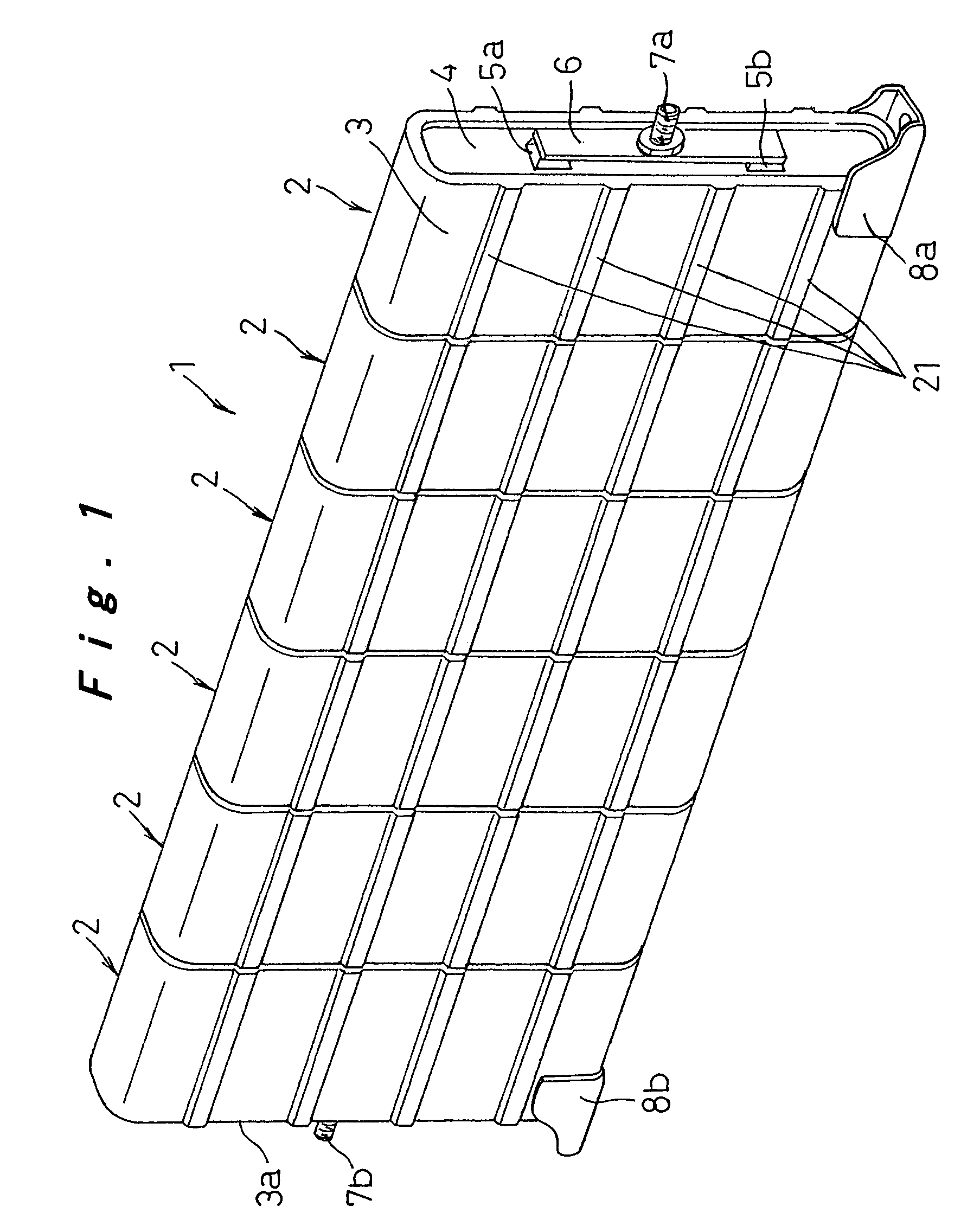
[0037]Hereinafter, a sealed rechargeable battery and a battery module according to a first embodiment of the present invention will be described with reference to FIGS. 1 to 6G.

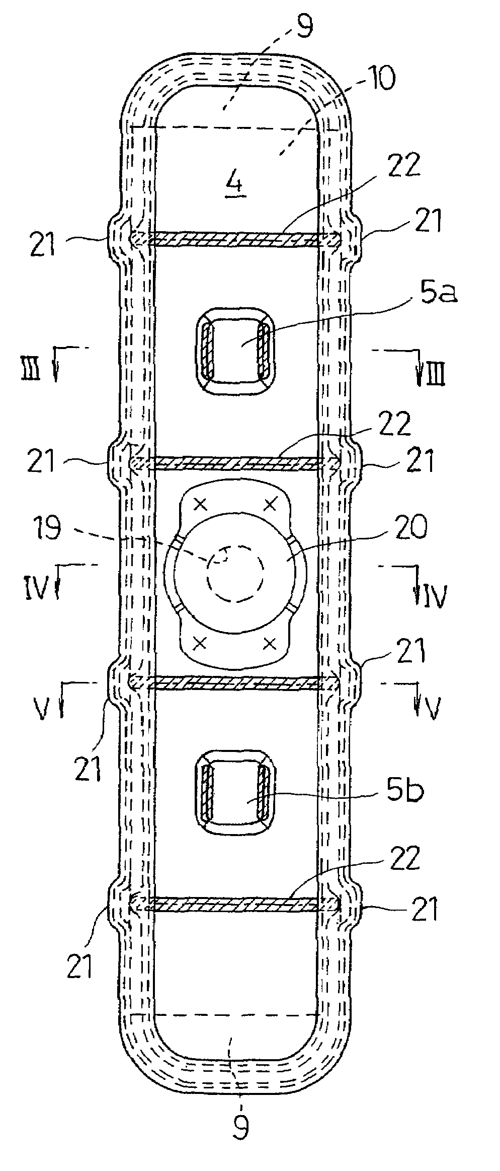
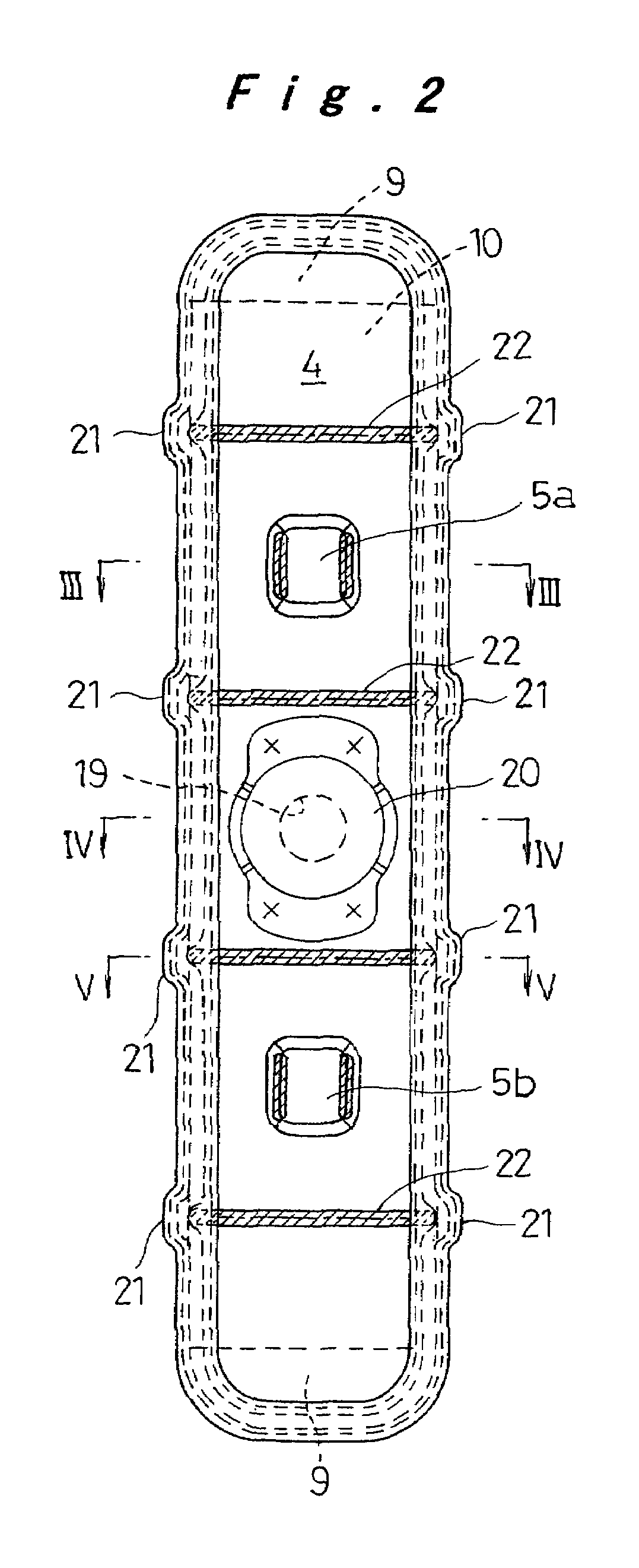
[0038]FIG. 1 shows a battery module 1 in which a plurality of (in the illustrated example, six) sealed rechargeable batteries 2 are arranged in a row so as to be integrally and electrically connected to each other in series. Each of the sealed rechargeable batteries 2 is constituted by sealing one open end of an approximately prismatic metal case 3 having a rounded rectangular cross section with a meal sealing plate 4. Each of the case 3 and the sealing plate 4 is constituted by a steel plate plated with nickel so as to ensure the resistance against an electrolyte solution. Moreover, the sealing plate 4 is constituted by a steel plate having a large thickness so as to ensure the strength and the rigidity of the opening of the case 3.

[0039]A pair of connection projections 5a and 5b are formed on the sealing pl...

second embodiment

[0057]Next, a sealed rechargeable battery according to a second embodiment of the present invention will be described with reference to FIGS. 9 to 11E. The same components as those in the first embodiment are denoted by the same reference numerals, and the description thereof will be omitted.

[0058]In this second embodiment, as shown in FIGS. 9 and 10, current collectors 31 and 32 are respectively bonded to the positive electrode end face 14 and the negative electrode end face 15 with welding portions 33 through laser beam welding or electron beam welding. In the illustrated example, the welding portions 33 are provided at five positions at appropriate intervals.

[0059]A connection projection 34 is provided for the current collector 31. The connection projection 34 penetrates a sealing plate 36 through an insulating member 35 to externally project therefrom. An engagement ring 38, which is abutted against the outer face of the sealing plate 36 through an insulating plate 37, is engage...


PUM


Abstract

A sealed rechargeable battery includes: a metal case having an elliptical or rectangular cross section; a metal sealing plate for sealing an opening at one end of the case; and an electrode plate assembly being housed in the case with an electrolyte solution. In this configuration, a plurality of projecting ridges are formed in a continuous or discontinuous manner on both longer side faces of the case between a bottom face and the opening so as to enhance the cooling performance and to improve the strength of the side faces of the case.

Description

[0001]The present disclosure relates to subject matter contained in priority Japanese Patent Application No. 2002-274800, filed on Sep. 20, 2002, the contents of which is herein expressly incorporated by reference in its entirety.BACKGROUND OF THE INVENTION[0002]1. Field of the Invention[0003]The present invention relates to a sealed rechargeable battery and a battery module, in particular, to a sealed rechargeable battery constituted by housing an electrode plate assembly in a metal case having an elliptical or a rectangular cross section and a battery module constituted by connecting the sealed rechargeable batteries in series.[0004]2. Description of Related Art[0005]As a sealed rechargeable battery used as a power source for electric vehicle and hybrid car, a lithium ion rechargeable battery or a nickel metal hydride battery has been put into practical use.[0006]As this type of sealed rechargeable battery, a sealed rechargeable battery having the following structure is convention...

Claims


Application Information

Patent Timeline
IPC IPC(8): H01M2/26H01M10/04H01M50/103H01M50/176H01M50/184H01M50/186H01M50/191H01M50/503H01M50/51H01M50/516H01M50/528
CPCH01M2/0202H01M2/0237H01M2/06H01M2/08H01M2/204H01M2/206H01M10/5053H01M10/5004H01M10/5016H01M10/5032H01M10/5046H01M10/625H01M10/647H01M10/6551H01M10/6554H01M10/613Y02E60/10Y02P70/50H01M50/184H01M50/516H01M50/186H01M50/103H01M50/51H01M50/503H01M50/176H01M50/191
Inventor HAMADA, SHINJIETO, TOYOHIKO
Owner PANASONIC CORP
Why Eureka
Try Eureka