
Storage system and storage management method

a storage system and management method technology, applied in the field of storage system and storage system management method, can solve the problems of increasing the load on the one secondary storage control device, the inability to provide data processing services to the host, and the structure becomes complex

Inactive Publication Date: 2008-12-09
HITACHI LTD
View PDF4 Cites 36 Cited by
  • Summary
  • Abstract
  • Description
  • Claims
  • Application Information

AI Technical Summary

Benefits of technology

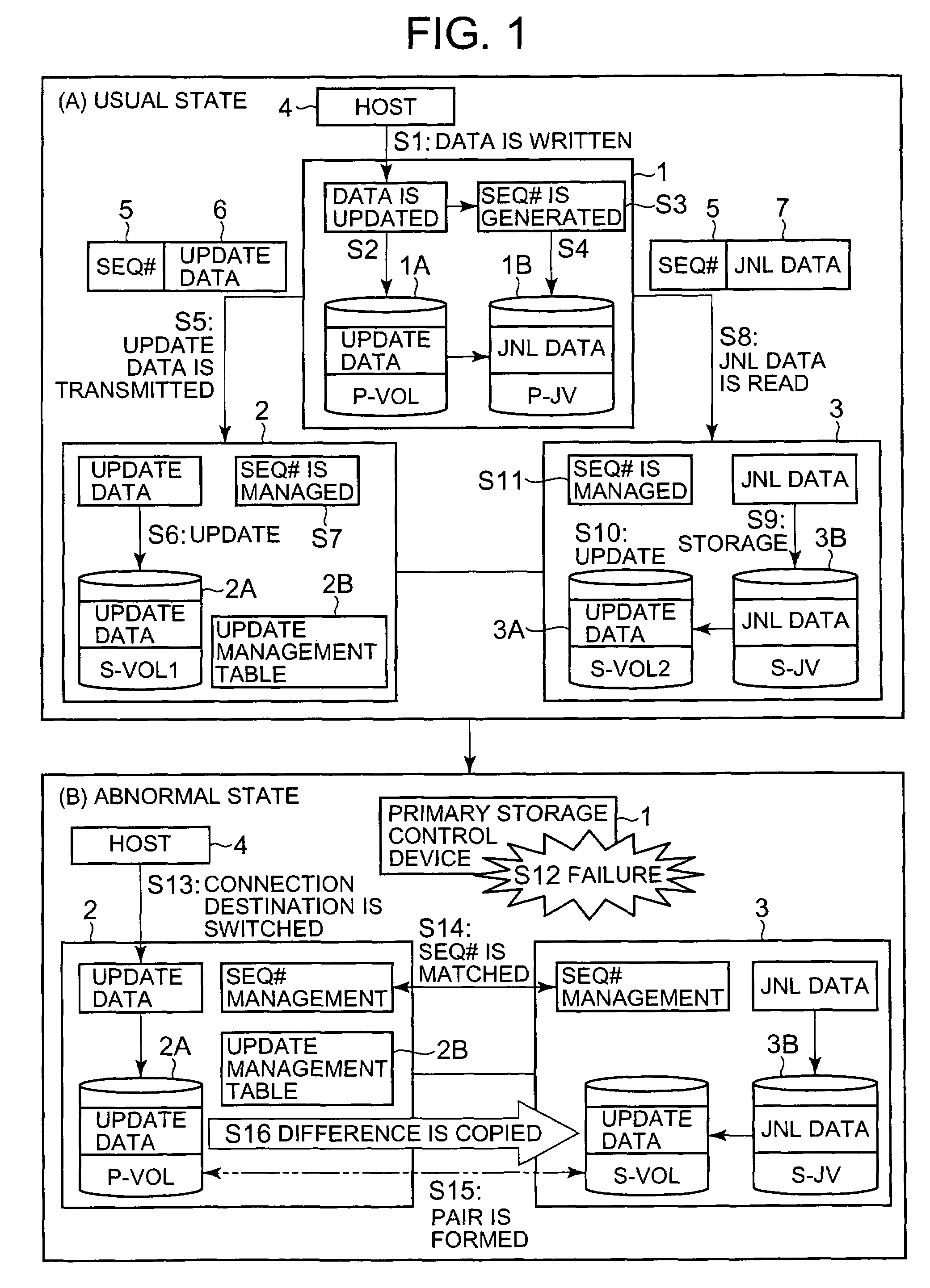
[0011]Thus, if the first storage control device receives write data from the upper-level device, it saves the journal data for which a management number was set and transmits the management number and write data to the second storage control device. The management number is a number for managing the order of data update and is generated, for example, as a sequence of numbers increasing by one each time data update is conducted. The second storage control device updates the second data volume synchronously with the update of the first data volume. The third storage control device updates the third data volume by acquiring the journal data stored in the first journal volume at the appropriate timing. Therefore, the contents of the first data volume and second data volume are synchronized and it is possible that a difference in the storage contents occurs between the first data volume or second data volume and the third data volume. The second storage control device stores the update number and write data in the update management table. Therefore, the second storage control device is not required to generate journal data based on the command from the first storage control device and is not required to provide a volume for saving the journal data.
[0012]In one implementation mode, when a copy pair is formed by taking the second data volume as a primary volume and the third data volume as a secondary volume, the second control unit notifies the upper-level device to the effect that switching from the first storage control device to the second storage control device has been completed. Thus, the upper-level device is notified about the switching completion before the storage contents of the second data volume and third data volume are matched. As a result, the switching time can be shortened and usability is increased.
[0013]In one implementation mode, in the case of switching from the first storage control device to the second storage control device, the second control unit transmits to the third control unit the management number following the newest management number that is held in the third control unit and write data corresponding to the storage control device number. Thus, the second storage control device transmits to the third storage control device the write data and management number only representing the difference between the second data volume and third data volume. As a result, the second data volume and the third data volume can be synchronized within a comparatively short time and usability is increased.
[0015]In one implementation mode, the second control unit copies the entire storage contents of the second data volume into the third data volume when the newest management number has not been registered in the update management table. As a result, a copy pair of the second data volume and third data volume can be formed and the redundancy of the system can be ensured.
[0016]In one implementation mode, the first, second and third control units get hold in advance of the correspondence and relationship of the first, second, and third data volume and the correspondence and relationship of the first and second journal volumes. Therefore, in the case of switching from the first storage control device to the second storage control device, the second storage control device can rapidly form a copy pair of the second data volume and third data volume and can shorten the switching time.
[0017]In another implementation mode, the second control unit gets hold in advance of the correspondence and relationship of the first data volume and the second data volume, and the third control unit gets hold in advance of the correspondence and relationship of the first data volume and the third data volume and the correspondence and relationship of the first journal volume and the second journal volume. When switching is made from the first storage control device to the second storage control device, the second control unit acquires confirmation information for confirming the correspondence and relationship of the second data volume and the third data volume from the third control unit and forms the copy pair of the second data volume and the third data volume based on the acquired confirmation information. Thus, the second control unit confirms the presence of the third volume that has to be synchronized with the second volume and forms a copy pair based on the confirmation information acquired from the third control unit. As a result, the second control unit and third control unit may hold only the correspondence and relationship with the first storage control device and the storage volume necessary for storing the correspondence and relationship can be reduced.

Problems solved by technology

However, when a failure occurs in the only available backup site before the main site is recovered, the data processing service cannot be provided to the host.
However, because one secondary storage control device has to generate the journal data each time data update is conducted, the load on the one secondary storage control device increases.
Another problem is that a volume for saving the journal data in the one storage control device has to be provided and the structure becomes complex.

Method used


Image

  • Storage system and storage management method
  • Storage system and storage management method
  • Storage system and storage management method

Examples


working example 1

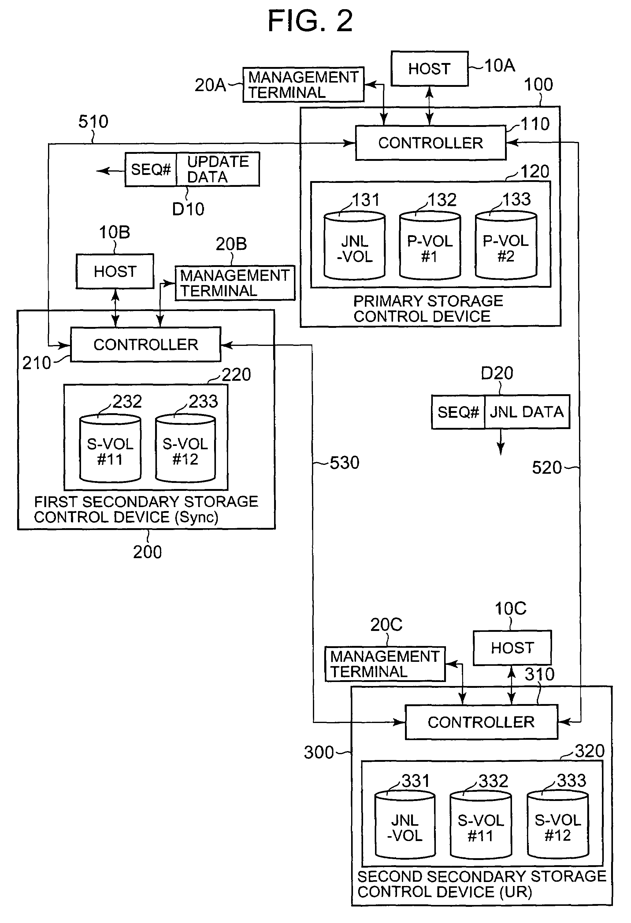
[0060]FIG. 2 is an explanatory drawing illustrating the entire configuration of the storage system in accordance with the present invention. As for the correspondence and relationship with FIG. 1, a primary storage control device 100 corresponds to the primary storage control device 1 shown in FIG. 1, a first secondary storage control device 200 corresponds to the first secondary storage control device 2 in FIG. 1, a second secondary storage control device 300 corresponds to the second secondary storage control device 3 in FIG. 1, and a host 10A corresponds to the host 4 in FIG. 1.

[0061]This storage system can be configured by comprising at least one primary storage control device 100, a plurality of secondary storage control devices 200, 300, hosts 10A, 10B, 10C, and management terminals 20A, 20B, 20C. At least some of the hosts 10A, 10B, 10C, and management terminals 20A, 20B, 20C may be identical. For example, the host 10A and the host 10B may be the same device, and the manageme...

embodiment 2

[0158]The second embodiment of the present invention will be explained based on FIG. 19. The below-described embodiments, including the present embodiment, are equivalent to modifications of the first embodiment. In the present embodiment, the redundancy of the storage system is improved by using four storage control devices.

[0159]FIG. 19(a) is an explanatory drawing illustrating the usual state. This storage system comprises a third secondary storage control device 400 in addition to the primary storage control device 100, first secondary storage control device 200, second secondary storage control device 300.

[0160]As was described in the first embodiment, the primary storage control device 100 and the first secondary storage control device 200 are connected by a synchronous method and the primary storage control device 100 and the second secondary storage control device 300 are connected by an asynchronous method.

[0161]FIG. 19(b) is an explanatory drawing illustrating the state wh...

embodiment 3

[0164]The third embodiment will be explained based on FIG. 20. In the present embodiment, the storage control devices 100, 200, 300 do not hold the correspondence and relationship with each of the storage control devices 100, 200, 300, and the secondary storage control devices 200, 200 hold the correspondence and relationship only with the primary storage control device 100.

[0165]FIG. 20 is a flowchart illustrating part of the processing executed in the storage system of the third embodiment. This flowchart corresponds to the flowchart explained with reference to FIG. 15 and the two flowcharts have common steps. The explanations of common steps is herein omitted and the explanation will be focused only on the steps specific to the third embodiment.

[0166]After step S59, the host 10B requests the transmission of pair confirmation information from the second secondary storage control device 300 (S91). The pair confirmation information is information for confirming the correspondence an...


PUM


Abstract

The storage system of the present invention has a simple configuration and ensures redundancy of the system. The primary storage control device and the first secondary storage control device are connected by a synchronous read method, and the primary storage control device and the second secondary storage control device are connected by an asynchronous read method. The primary storage control device sets a management number in the update data and saves a journal data. The primary storage control device associates the management number with the update data and transmits them to the first secondary storage control device. The first secondary storage control device writes the update data to the first secondary volume, associates the management number with the storage destination address of the update data and stores them in the maintenance table. If the primary storage control device stops, the first secondary storage control device becomes anew a primary storage control device. The first secondary storage control device is connected to the second secondary storage control device by an asynchronous read method.

Description

CROSS-REFERENCE TO RELATED APPLICATIONS[0001]This application relates to and claims priority from Japanese Patent Application No. 2005-243568 filed on Aug. 25, 2005, the entire disclosure of which is incorporated herein by reference.BACKGROUND OF THE INVENTION[0002]1. Field of the Invention[0003]The present invention relates to a storage system and a storage system management method.[0004]2. Description of the Related Art[0005]A storage system, for example, comprises at least one storage control device called a disk array subsystem and provides data storage service to a host computer (referred to hereinbelow as “host”). In a storage control device, a large number of disk drives can be arranged as an array, and a storage area based on RAID (Redundant Array of Independent Disks) can be created.[0006]Furthermore, a backup site can be disposed in a location remote from the main site to cope with a large-area accident, this being known as the so-called disaster recovery system. A storage...

Claims


Application Information

Patent Timeline
Patent Type & Authority Patents(United States)
IPC IPC(8): G06F12/00G06F12/16
CPCG06F11/2058G06F11/2074G06F11/2076G06F11/2082G06F3/0617G06F3/065G06F3/067
Inventor SANO, KAZUHIDEOKUMOTO, KATSUHIROHONMA, HISAONINOSE, KENTAARAKAWA, HIROSHI
Owner HITACHI LTD
Learn More