Actuator

a technology for actuators and actuators, applied in the field of actuators, can solve the problems of reducing the efficiency of power transmission, affecting the performance of the actuator, and the failure to eliminate axial loads on the actuator motor shaft, so as to improve the inside structure of the actuator, improve the power transmission efficiency, and eliminate the phenomenon of clicking noise

Inactive Publication Date: 2008-12-16
SCHUKRA OF NORTH AMERICA
View PDF15 Cites 19 Cited by
  • Summary
  • Abstract
  • Description
  • Claims
  • Application Information

AI Technical Summary

Benefits of technology

[0017]One aspect of the invention reduces the motor axial force of lumbar support actuators and eliminates the click noise phenomena. Another aspect optimizes inside structure of the actuator and increases power transmission efficiency. Another aspect eliminates the breakage of the gear teeth of the actuator. The invention eliminates the shaft force of the motor, optimizes the inner structure of the gear box, increases the transmission efficiency, and reduces the possibility of broken teeth and broken cables

Problems solved by technology

This design fails to eliminate axial loads on the actuator motor shaft.
Consequently, it causes the shaft to move axially in its housing and hit the end of it repeatedly, producing an undesirable clicking noice.
The single worm / worm wheel meshing design also has a lower efficiency for power transmission and requires a higher reduction rate if the other conditions are the same.
Typically, the worm and worm wheel module is undersized to save space, and the insufficient mechanical strength of the single worm / worm wheel transmission often results in tooth breakage.
The axial motion causes rapid wear of the washer at the end of the shafts.

Method used


Image

  • Actuator
  • Actuator
  • Actuator

Examples


first embodiment

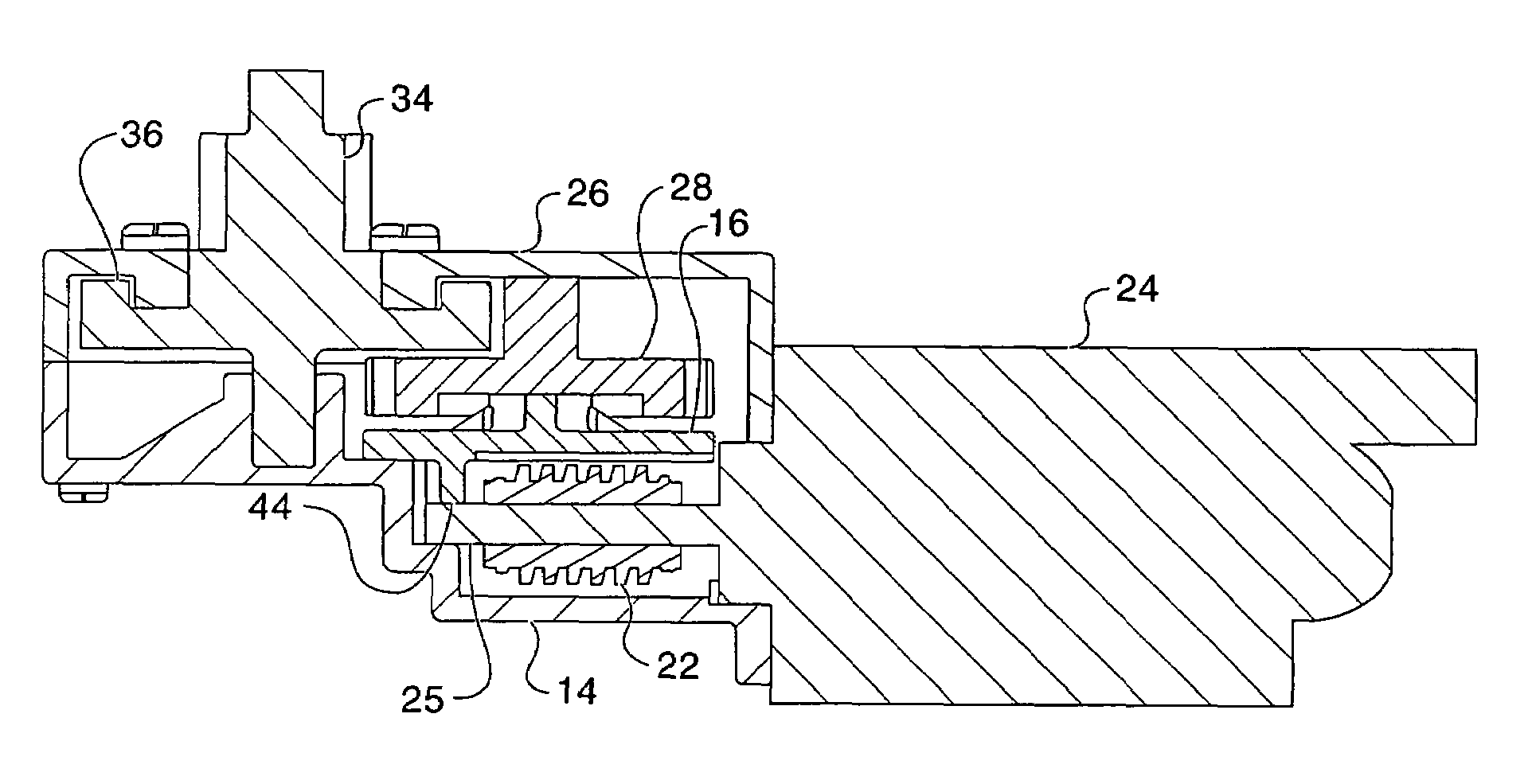
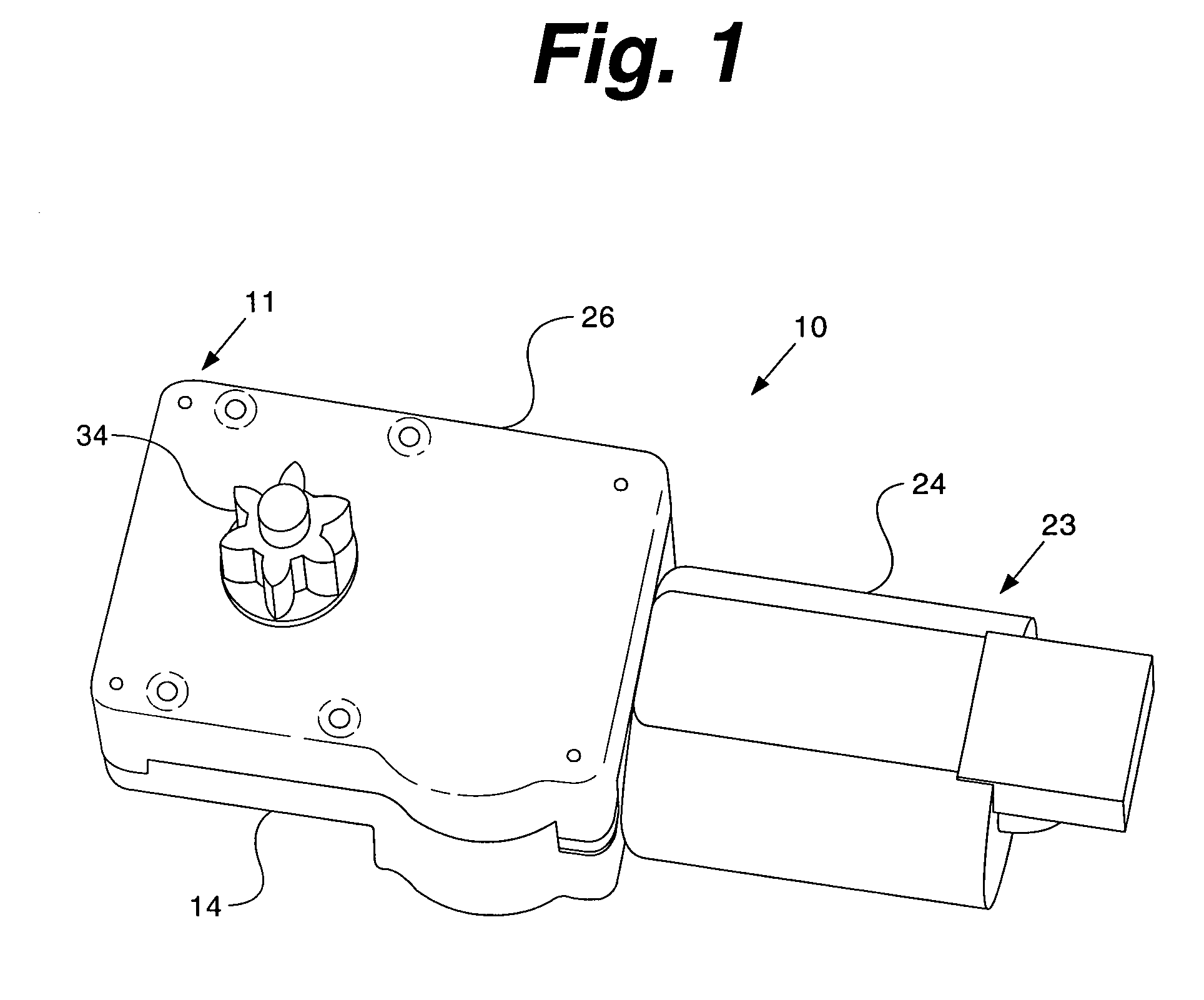
[0030]Referring to the accompanying drawings in which like reference numbers indicate like elements, FIG. 1 illustrates an actuator in a first embodiment, generally indicated by numeral reference 10. The actuator includes a motor assembly 23 and a gearbox assembly 11. The motor assembly 23 is connected to the gearbox assembly 11 and includes a motor 24. The gearbox assembly 11 includes multiple stages of gear reduction. The gearbox assembly includes a gearbox housing 14 and a gearbox cover 26. The gearbox cover 26 is adapted for mounting on the gearbox housing 14. In the depicted embodiment, an output member 34 protrudes through the gearbox cover 26.

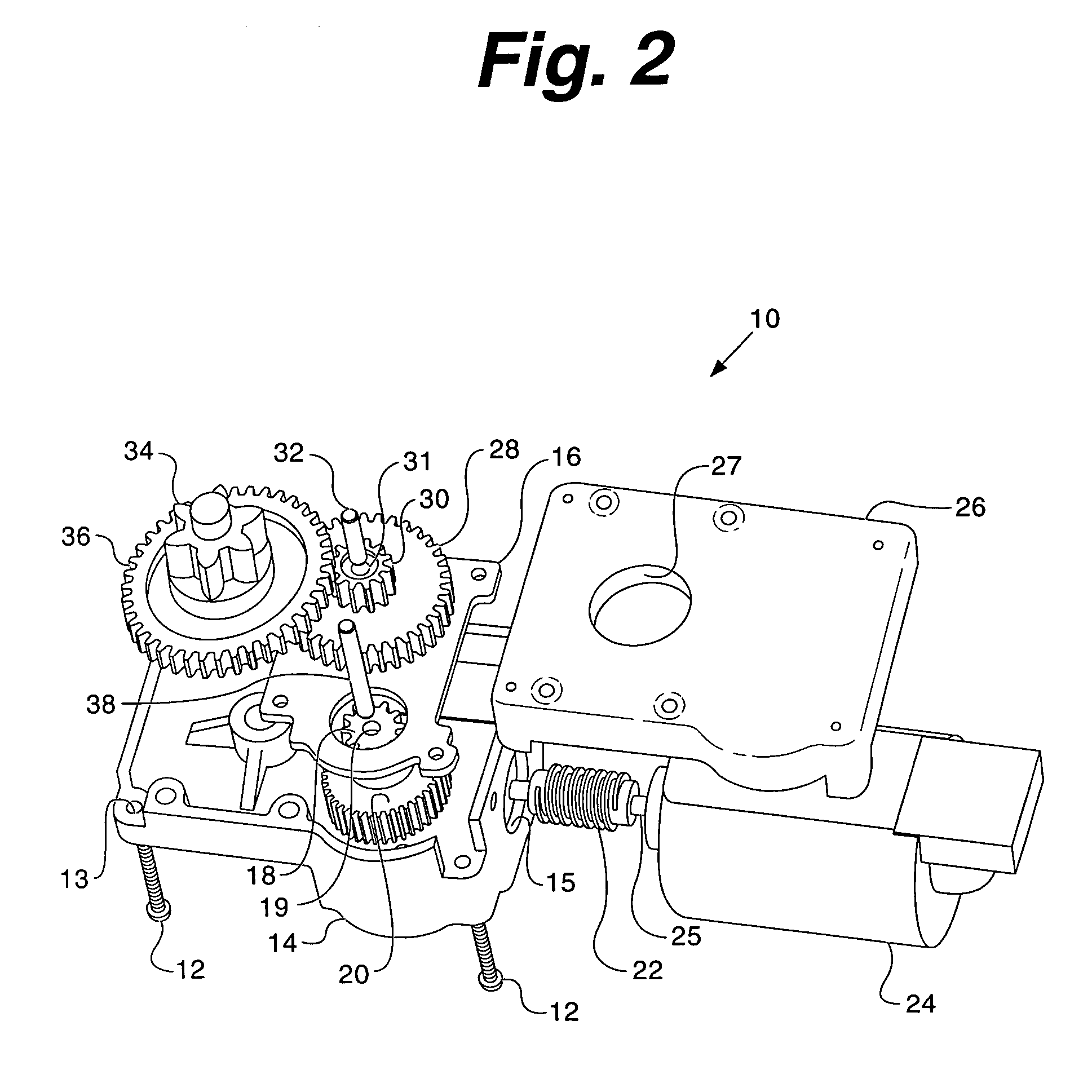
[0031]FIG. 2 illustrates an exploded view of the actuator 10, and FIG. 3 illustrates an assembled view of the actuator 10. The motor 24 includes an output shaft 25. A worm 22 is mounted on the output shaft 25. In the depicted embodiment, the worm 22 is made of plastic, for example, polyoxymethylen (POM) material. The worm 22 drives a wor...

second embodiment

[0043]FIGS. 6, 7 and 8 illustrate the actuator, generally indicated by numeral reference 100. The actuator 100 includes a motor 124 and gearbox housing 119. A worm 122 is connected to a drive shaft of the motor 124. The worm 122 has two tooth portions, each having opposing helix directions. The teeth on a first half 122a are in right-hand helix direction and those on the second half 122b are in left-hand helix direction. While in the depicted embodiments a single worm component 122 has two tooth portions, those skilled in the art would understand that two worm components, each having its own helix direction, could equally be used and assembled in tandem on the shaft.

[0044]The worm 122 drives a right-hand worm gear 120 and a left-hand worm gear 128. In other words, the single-lead worm 122 drives a first worm gear 120 with a right-hand helix tooth direction and a second worm gear 128 with a left-hand helix tooth direction. Thus, the first stage of gear reduction has two sets of worm / ...


PUM


Abstract

An actuator for an automotive seat that includes two main assemblies: (1) a motor assembly; and (2) a gearbox assembly. The gearbox assembly includes multiple stages of gear reduction and a dividing plate. In some embodiments, the gearbox assembly has a single-lead worm, a worm gear with a right-hand helix tooth direction, and a worm gear with a left-hand helix tooth direction. The worm gears are driven by the single-lead worm. The single-lead worm has two ends, one end has a right-hand tooth helix direction, and the other end has a left hand helix direction.

Description

CROSS-REFERENCE TO RELATED APPLICATIONS[0001]This application claims priority of U.S. Provisional Application No. 60 / 627,628, filed Nov. 11, 2004.STATEMENT REGARDING FEDERALLY SPONSORED RESEARCH OR DEVELOPMENT [0002]Not Applicable.APPENDIX[0003]Not Applicable.BACKGROUND OF THE INVENTION [0004]1. Field of the Invention[0005]This invention relates generally to actuators and, more particularly, to a transmission improvement for an actuator.[0006]2. Related Art[0007]Many mechanical devices need to be moved to a user selected position and then held there against a force that is biased to return the device to its original position. Such devices are commonly used for ergonomic supports in seating, especially lumbar supports for automobile seats. Lumbar supports exert a comfortable force against the lumbar spine of a seat occupant. This force is applied mechanically through a wide variety of configurations including arching, bending, tightening, extending or otherwise moving a pressure surf...

Claims


Application Information

Patent Timeline
Patent Type & Authority Patents(United States)
IPC IPC(8): F16H1/16
CPCF16H37/06B60N2002/0236Y10T74/19823Y10T74/19698Y10T74/19828B60N2/02253
Inventor LI, ZHIHANGLI, SAILITANG, LIMINGDU, XU
Owner SCHUKRA OF NORTH AMERICA
Why Eureka
Try Eureka