In-vehicle electronic control unit

a technology of electronic control unit and vehicle, which is applied in the direction of electric controller, program control, instruments, etc., can solve the problems of late abnormality determination or waste of transmission, and achieve the effect of alleviating the control load on the second control circuit portion

Active Publication Date: 2008-12-16
MITSUBISHI ELECTRIC CORP
View PDF14 Cites 8 Cited by
  • Summary
  • Abstract
  • Description
  • Claims
  • Application Information

AI Technical Summary

Benefits of technology

[0012]The present invention is directed to a solution to the above described disadvantages, and it is an object of the invention to provide an in-vehicle electronic control unit that can transmit digital conversion values based on many analog signals efficiently and highly frequently from the second control circuit portion to the first control circuit portion while alleviating the control load.
[0022]By the in-vehicle electronic control unit according to the invention, periodic reporting is prohibited at the start of engine operation, various kinds of constant setting are carried out intensively by the periodic transmission means, and thus periodic reporting is permitted after the initialization is complete, so that the control circuit portions carry out input monitoring by periodic reporting and output control by periodic reporting to each other. In this way, the microprocessor provided in the first control circuit portion can permit or stop AD conversion to the multi-channel AD converter provided in the second control circuit portion.
[0025]If periodic reporting is permitted, AD conversion operation can be carried out / stopped, so that AD conversion operation at frequency higher than necessary can be reduced, and the control load on the second control circuit portion can be alleviated.

Problems solved by technology

In addition, abnormality determination about the AD converter is carried out after the AD converted-digital information is transmitted, and therefore abnormality determination may be late or transmission may be wasted.

Method used


Image

  • In-vehicle electronic control unit
  • In-vehicle electronic control unit
  • In-vehicle electronic control unit

Examples


first embodiment

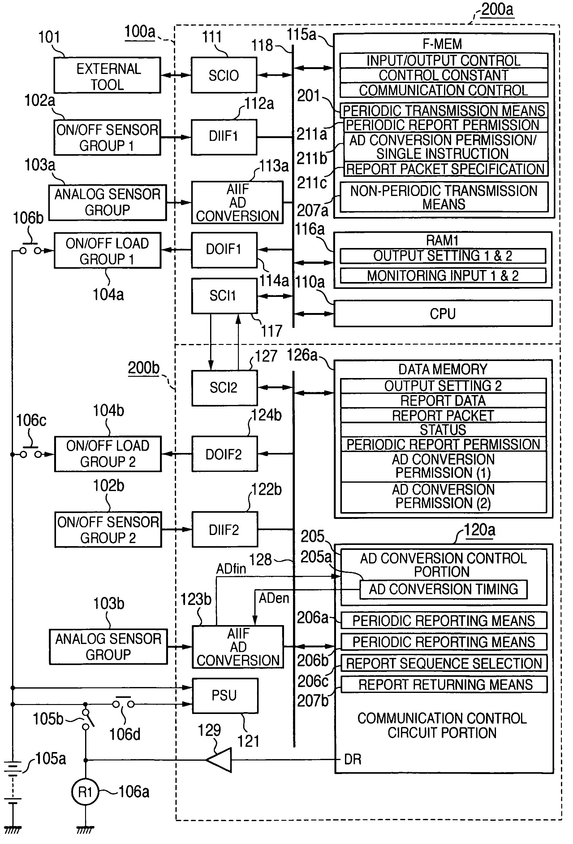
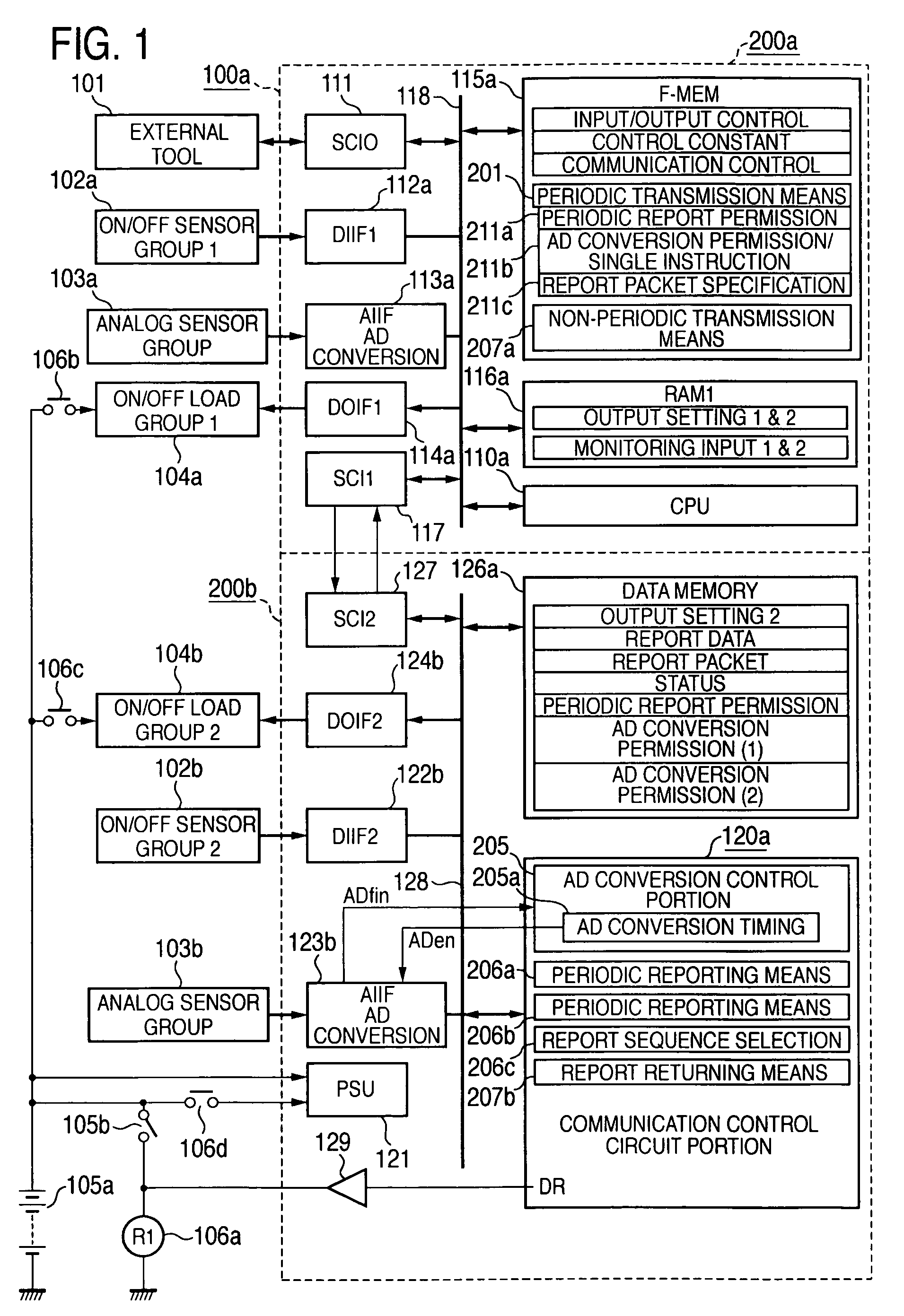
[0034]Now, the configuration of a first embodiment of the invention will be described in conjunction with FIG. 1.

[0035]FIG. 1 is a block diagram of the configuration of an in-vehicle electronic control unit according to the first embodiment of the invention.

[0036]In FIG. 1, the in-vehicle electronic control unit 100a includes a first control circuit portion 200a and a second control circuit portion 200b.

[0037]Firstly, elements connected to the outside of the in-vehicle electronic control unit 100a will be described.

[0038]An external tool 101 is connected to the in-vehicle electronic control unit 100a through a detachable connector to transfer and write control programs and control constants in a non-volatile program memory 115a (that will be described) when the product is shipped or inspected for maintenance purposes.

[0039]A first input sensor group 102a carries out ON / OFF operations at relatively high speed and high frequency and signals therefrom must directly be obtained by a mi...

second embodiment

[0209]Now, a second embodiment of the invention will be described mainly about the difference from the first embodiment.

[0210]FIG. 8 is a block diagram of the configuration of the in-vehicle electronic control unit according to the second embodiment of the invention.

[0211]In FIG. 8, the in-vehicle electronic control unit 100b includes a first control circuit portion 210a and a second control circuit portion 210b, and the part other than the second control circuit portion 210b is the same as that in FIG. 1. The elements 121, 122b, 123b, 124b, 127, 128 and 129 included in the second control circuit portion 210b in FIG. 8 are the same as those in FIG. 1. The second control circuit 210b in FIG. 8 has an auxiliary CPU 120b (microprocessor), an auxiliary program memory 125 and an auxiliary RAM memory 126b. The auxiliary program memory 125 stores AD conversion timing specifying means 205a, periodic reporting means 206a and 206b, report sequence selecting means 206c, and report returning me...


PUM


Abstract

A first control circuit portion carries out input / output control in cooperation with a microprocessor, a program memory, and a RAM memory. A second control circuit portion is in cooperation with the communication control circuit portion and the data memory to carry out serial communication with the first control circuit portion. A switch signal input to the second control circuit portion is stored in a first report packet, a digital conversion value for an analog signal input is stored in a second report packet, and the first and second packets are alternately periodically transmitted to the first control circuit portion. A multi-channel AD converter included in an analog signal input circuit starts to carry out AD conversion a prescribed time period after a first report packet is transmitted and finishes conversion before a second report packet is transmitted, so that up-to-date AD conversion data is transmitted.

Description

BACKGROUND OF THE INVENTION[0001]1. Field of the Invention[0002]The invention relates to an in-vehicle electronic control unit having first and second control circuit portions that are electrically separated and serially communicate monitoring signal and control signal to each other.[0003]2. Description of the Related Art[0004]There have been known in-vehicle electronic control unit including first and second control circuit portions that are electrically separated and serially communicate monitoring signal and control signal to each other, by using of periodic transmission packets for down link communication, periodic report packets for up link communication, and report return packets for up link communication corresponding to reading request packets as down link communication and the like.[0005]The “in-vehicle electronic control unit” disclosed by Patent Document 1: Japanese Patent Laid-Open No. 2003-285702 (paragraph No. 0079, FIG. 2) for example includes a microprocessor connect...

Claims


Application Information

Patent Timeline
Patent Type & Authority Patents(United States)
IPC IPC(8): G06F7/00
CPCH04L12/2854
Inventor IWAGAMI, YUKITANAKA, JUNYAYAMASHITA, MANABUHASHIMOTO, KOHJI
Owner MITSUBISHI ELECTRIC CORP
Why Eureka
Try Eureka