
Sensor arrangement for measuring a pressure and a temperature in a fluid

a technology of fluid pressure and temperature, applied in the direction of instruments, heat measurement, heating types, etc., can solve the problems of leakage, wear in the construction, etc., and achieve the effect of reducing the flow effect, increasing the strain, and reducing the strain

Active Publication Date: 2008-12-23
SENSATA TECHNOLOGIES INC
View PDF22 Cites 46 Cited by
  • Summary
  • Abstract
  • Description
  • Claims
  • Application Information

AI Technical Summary

Benefits of technology

The present invention provides a combined temperature and pressure sensing arrangement that can be used in high temperature ranges and is fully hermetic. The arrangement includes a metallic membrane structure which passes on the temperature and pressure of the fluid to the temperature sensitive electrical element and pressure sensing electrical element, resulting in a compact and efficient sensor arrangement. The membrane structure is designed to minimize leakage and wear and tear in the sensor arrangement. The arrangement also includes a sealing member to improve thermal isolation and prevent fluid leakage. The technical effects of the invention include good dynamic response, accurate temperature and pressure sensing, and efficient and reliable operation.

Problems solved by technology

Furthermore, using one metallic membrane to pass on both temperature and pressure reduces the possibility of leakage.
Normally, said materials could be peeled off or cause wear in the construction.

Method used


Image

  • Sensor arrangement for measuring a pressure and a temperature in a fluid
  • Sensor arrangement for measuring a pressure and a temperature in a fluid
  • Sensor arrangement for measuring a pressure and a temperature in a fluid

Examples


Embodiment Construction

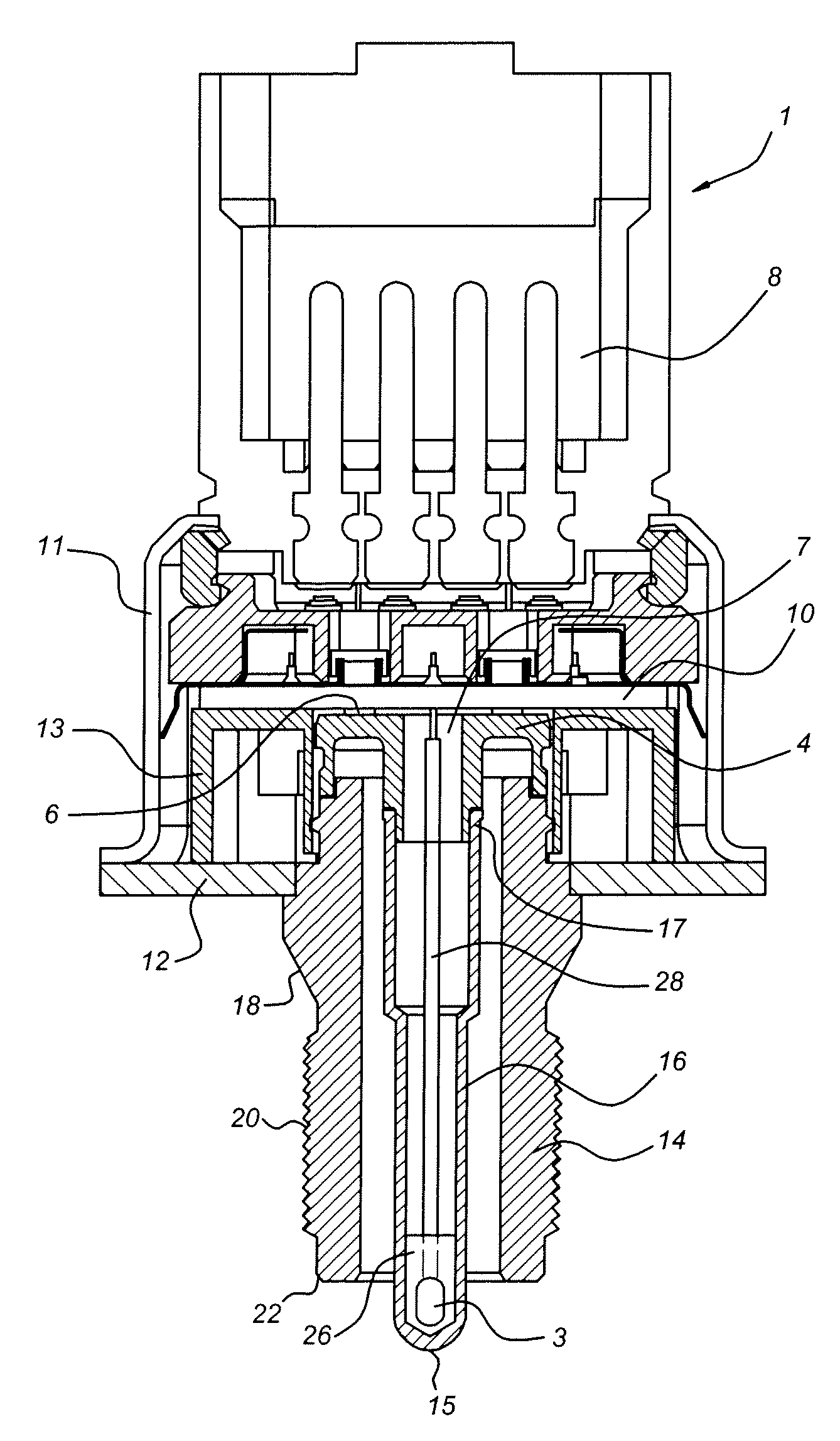
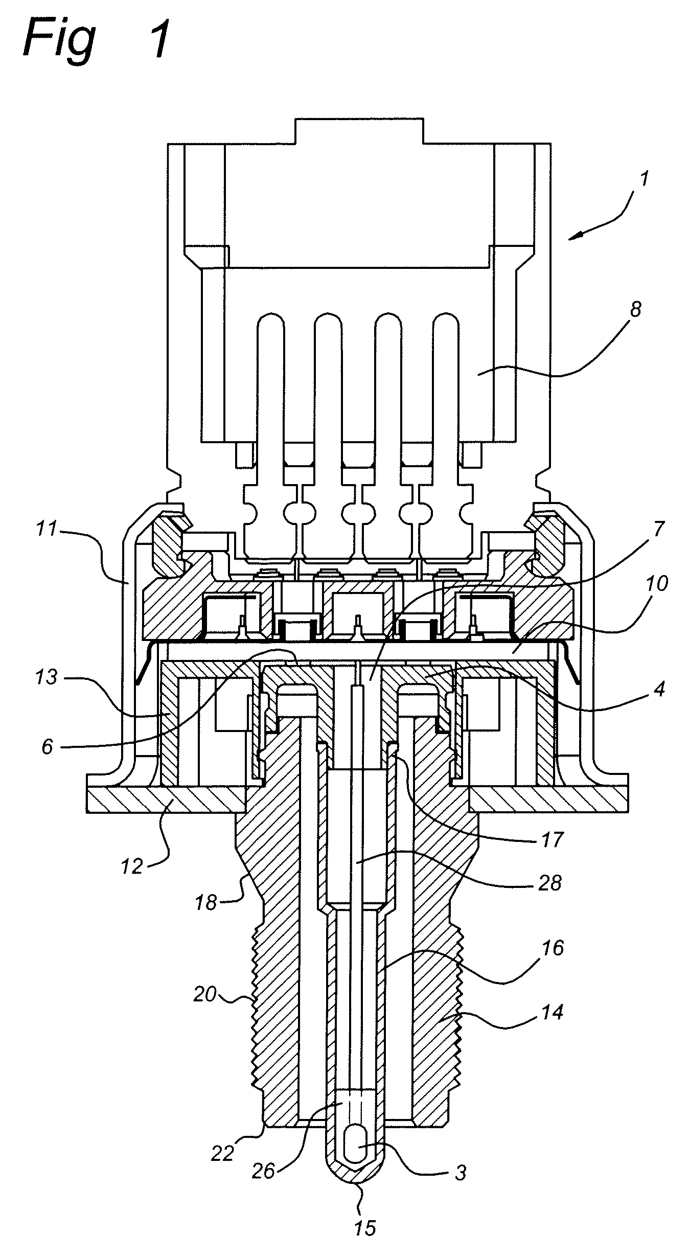
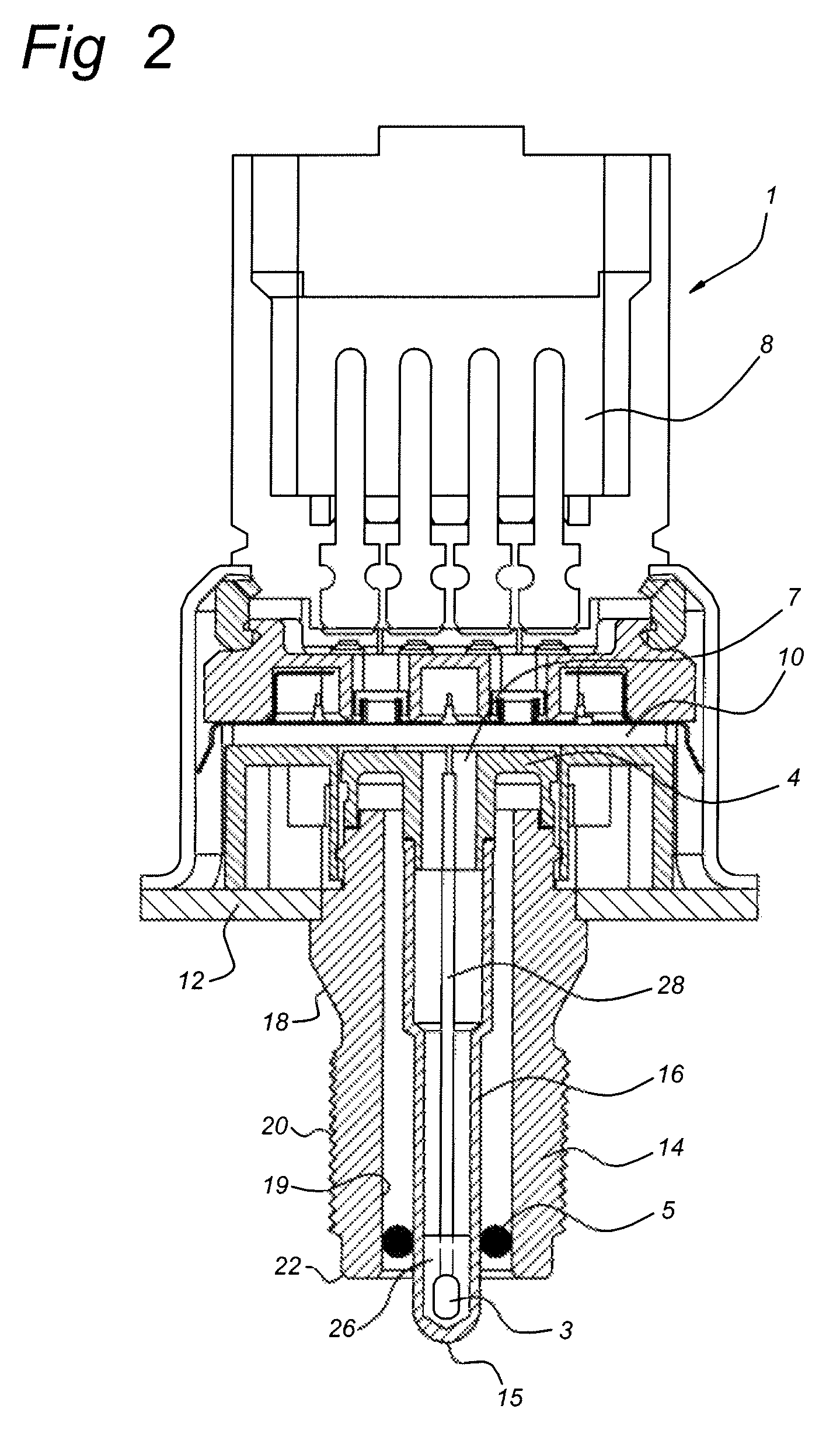
[0033]FIG. 1 illustrates a sectional view of a first embodiment of a sensor arrangement according to the present invention. The sensor arrangement 1 comprises a membrane structure 4, 16 both arranged in a common body 11, 12, 14. The membrane structure 4,16 includes an elongated body 16 and a pressure sensitive structure 4. The elongated body could be in the form of a metal tube, which is hermetically closed at one end. A temperature sensitive electrical element 3 is located at a closed end 15 of the elongated body 16. FIG. 6 shows a perspective view of the elongated body 16.

[0034]The temperature sensitive electrical element 3 could be any suitable Resistance Temperature Detectors (RTD), thermo couple or thermistor such as an NTC resistor. In order to measure accurately the temperature of the fluid, the closed end 15 of the elongated body 16 surrounding the temperature sensitive electrical element 3 should be immersed in the fluid to create a direct contact area with the fluid. Prefe...


PUM

PropertyMeasurementUnit
temperaturesaaaaaaaaaa
pressuresaaaaaaaaaa

Abstract

A sensor arrangement (1) for measuring a pressure and a temperature in a fluid is disclosed. The sensor arrangement (1) comprises a temperature sensitive electrical element (3) and a pressure sensing electrical element (6), the temperature sensitive electrical element (3) and pressure sensing electrical element (6) are both coupled to one side of a metallic membrane structure (4,16). The metallic membrane structure is arranged to pass on the temperature of the fluid which is at the other side of the membrane structure (4,16) to the temperature sensitive electrical element (3) and to pass on the pressure in the fluid to the pressure sensing electrical element (6). In this way a combined pressure and temperature sensor is obtained which is applicable in vehicle air-conditioning systems working with CO2 as refrigerant.

Description

RELATED APPLICATIONS[0001]Priority is claimed under European Patent Application No. 05111427.0, filed Nov. 29, 2005 and European Patent Application No. 06123975.2, filed Nov. 14, 2006.FIELD OF THE INVENTION[0002]The present invention relates generally to a sensor arrangement for measuring a pressure and a temperature in a fluid. The sensor arrangement comprising a temperature sensitive electrical element and a pressure sensing electrical element. The invention has particular application in vehicle air-conditioning systems working with CO2 as refrigerant. The arrangement according to the invention is also suitable for use in fuel injection systems in automotive applications.BACKGROUND OF THE INVENTION[0003]Today's, vehicle air conditioning systems working, with the refrigerant R134a, exhibit a pressure sensor on the “high pressure side” after the compressor usually for monitoring the operating pressure and for control. If the operating pressure exceeds a given maximum pressure, a reg...

Claims


Application Information

Patent Timeline
Patent Type & Authority Patents(United States)
IPC IPC(8): G01K13/00
CPCG01K13/02G01L9/0051G01L19/003G01L19/0092G01L19/14F25B2309/061F25B2700/19G01K2201/02
Inventor GENNISSEN, PAULUS THOMAS JOHANNESBORGERS, MARC GERARD JOHANKOLLING, ARIE-JANZWOLLO, CRIS RUIZAPPELO, ROGER MARCELKLEISSEN, WERNER JOHN PETER
Owner SENSATA TECHNOLOGIES INC
Learn More