Viewing angle control element, method of manufacturing the same, liquid crystal display device, and electronic apparatus

a technology of liquid crystal display device and control element, which is applied in the direction of polarising element, optics, instruments, etc., can solve the problems of narrow viewing angle, insufficient switching effect, and liquid crystal display device, and achieve the effect of lowering the contrast of the display, and reducing the switching

Active Publication Date: 2008-12-23
BOE TECH GRP CO LTD
View PDF16 Cites 19 Cited by
  • Summary
  • Abstract
  • Description
  • Claims
  • Application Information

AI Technical Summary

Benefits of technology

[0008]An advantage of the present invention to provide a viewing angle control element having a high switching effect between a wide viewing angle and a narrow viewing angle. The viewing angle control element can be used in a liquid crystal display device applicable to various utility environments and purposes.
[0009]A first aspect of the present invention is a viewing angle control element provided adjacent to a display device to control the viewing angle of the display device. The viewing angle control element includes a viewing angle control panel. The viewing angle control panel includes: a pair of transparent substrates; a liquid crystal layer interposed between the pair of transparent substrates and having hybrid-aligned liquid crystal molecules therein; and electric field applying unit for applying an electric field to the liquid crystal layer, wherein the alignment state of the liquid crystal molecules is changed by a voltage applied from the electric field applying unit to control the viewing angle of the display device.
[0010]There has already been known a technique of performing viewing angle control using a liquid crystal panel as in Japanese Unexamined Patent Application Publication No. 11-174489. However, the inventors of the present invention concluded that the limit of the viewing angle control effect in Japanese Unexamined Patent Application Publication No. 11-174489 results from using the chiral nematic liquid crystal, the homogeneous liquid crystal, the nematic liquid crystal having random alignment, or the like for the viewing angle control panel. That is, these types of liquid crystal originally contribute to only the lowering of contrast in display. On the contrary, the inventors found that, by using hybrid-aligned liquid crystal for the viewing angle control panel, the viewing angle could be greatly limited to a narrow viewing angle (when the viewing angle is limited) mode by reducing the amount of transmission light (by darkening the display) rather than by lowering the contrast of display on the wide viewing angle side. The reason why the amount of transmission light on the wide viewing angle side is changed by the variation of the arrangement state of the hybrid-aligned liquid crystal will be described in detail in later.
[0011]In the viewing angle control element according to the present invention, it is preferable that polarizing plates be provided on outer surfaces of the viewing angle control panel, respectively, and that absorption axes of the polarizing plates be arranged parallel to each other.
[0012]Further, in the present specification, the terms ‘outer surface’ and ‘inner surface’ of the liquid crystal panel or substrate are used. The term ‘inner surface’ means one of the main surfaces of each substrate facing the liquid crystal layer, and the term ‘outer surface’ means one of the main surfaces of each substrate opposite to the liquid crystal layer.
[0013]According to this structure, incident light is polarized into linearly polarized light by the polarizing plate on the incident side, and the linearly polarized light is incident on the liquid crystal layer having hybrid-aligned liquid crystal therein. Then, the linearly polarized light generates optical rotation in a predetermined direction of the azimuthal direction of the surface of the substrate, and appears to be dark under the parallel Nicols.

Problems solved by technology

Conventionally, liquid crystal display devices have a problem in that a viewing angle is narrow.
In Japanese Unexamined Patent Application Publication No. 11-174489, the switching of a viewing angle between a wide viewing angle and a narrow viewing angle is performed by the liquid crystal element for phase difference control, but a sufficient switching effect is not obtained in this case.
According to this structure, it is difficult to see the leakage of light from the viewing angle control panel by dispersing spacers.

Method used


Image

  • Viewing angle control element, method of manufacturing the same, liquid crystal display device, and electronic apparatus
  • Viewing angle control element, method of manufacturing the same, liquid crystal display device, and electronic apparatus
  • Viewing angle control element, method of manufacturing the same, liquid crystal display device, and electronic apparatus

Examples


first embodiment

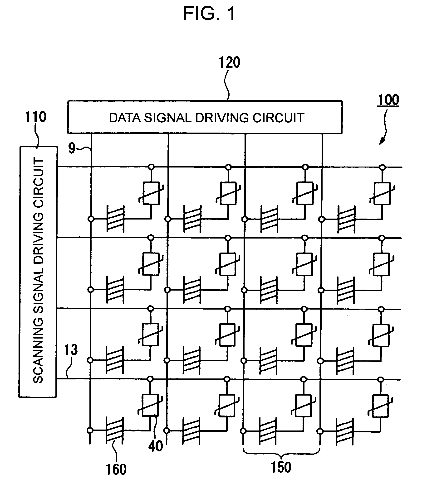
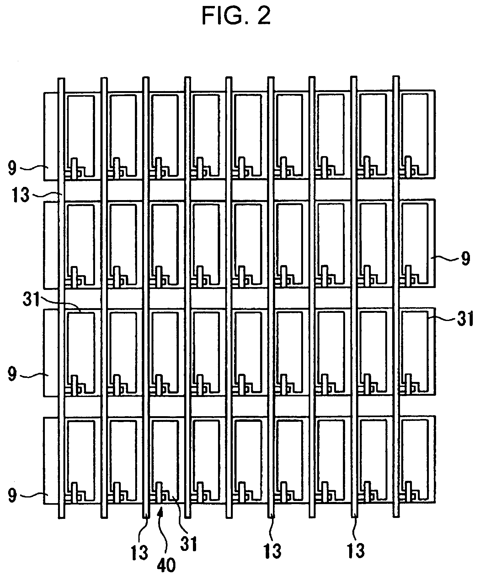
[0056]Hereinafter, the present invention will be described with reference to FIGS. 1 to 9.

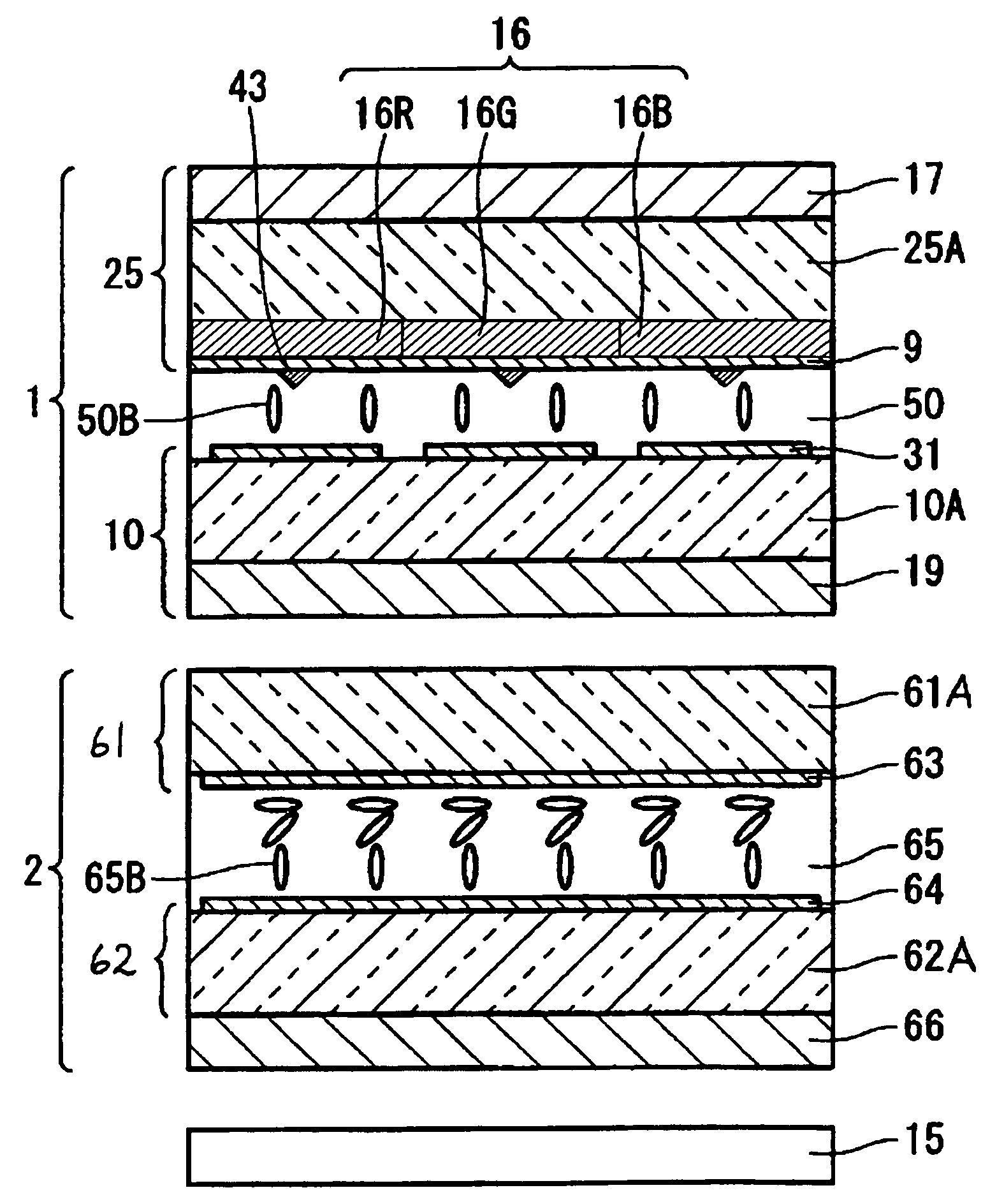
[0057]According to a liquid crystal display device of the present embodiment, a liquid crystal panel (cell) that controls viewing angle is stacked on a liquid crystal panel (cell) for display. The viewing angle control panel selectively restricts viewing angle characteristic of the display panel to a narrow viewing angle range. Therefore, it is preferable that the display panel be a liquid crystal mode with a wide viewing angle, such as a VAN (Vertically Aligned Nematic) mode or an IPS (In-Plane Switching) mode. In the present embodiment, VAN will be described as an example. Further, an active matrix transmissive liquid crystal display device using thin film diodes (hereinafter, referred to as TFDs) as pixel switching elements is taken as an example of the display panel. In addition, the reduced scale of each layer and member is different from the actual scale, such that each layer and each mem...

second embodiment

[0084]Hereinafter, the present invention will be described with reference to FIGS. 10 and 11.

[0085]The basic structure of a liquid crystal display device according to the present embodiment is the same as that in the first embodiment except that the relationship between the optical axes of the viewing angle control panel is different from that in the first embodiment. Therefore, only the different portion will be described below, and the description of the common portions will be omitted.

[0086]In the first embodiment, as shown in FIG. 5, the directions of the absorption axes of the second polarizing plate 66 and the third polarizing plate 19 are arranged parallel to each other in the vertical direction (the direction of 12 o'clock to the direction of 6 o'clock) of the display screen, and the slow axis direction of the liquid crystal layer 65 in the viewing angle control panel 2 is arranged so as to be parallel thereto. On the contrary, in the present embodiment, as shown in FIG. 10,...

third embodiment

[0090]Hereinafter, the present invention will be described with reference to FIG. 12.

[0091]In a liquid crystal display device according to the present embodiment, the structures of a display panel and a viewing angle control panel are the same as those in the first embodiment, but the structures of polarizing plates are different from those in the first embodiment. FIG. 12 is a cross-sectional view of the liquid crystal display device according to the present embodiment. In FIG. 12, the same components as those in FIG. 4 have the same reference numerals, and thus a description thereof will be omitted.

[0092]In the liquid crystal display device according to the present embodiment, as shown in FIG. 12, the first polarizing plate 17 is provided on the outer surface of the upper substrate 25 of the display panel 1, and the second polarizing plate 66 is provided on the outer surface of the lower substrate 62 of the viewing angle control panel 2. In the first embodiment, the third polarizi...


PUM

PropertyMeasurementUnit
thicknessaaaaaaaaaa
thicknessaaaaaaaaaa
diameteraaaaaaaaaa

Abstract

A liquid crystal display device includes a display panel and a viewing angle control panel. The viewing angle control panel includes a pair of substrates, a liquid crystal layer interposed between the pair of substrates, and a pair of electrodes for applying an electric field to the liquid crystal layer. The liquid crystal layer is composed from hybrid-aligned liquid crystal molecules. The viewing angle of the display panel is controlled by changing an alignment state of the hybrid-aligned liquid crystal molecules in the liquid crystal layer by voltage applied by the electrodes.

Description

RELATED APPLICATIONS[0001]This application claims priority to Japanese Patent Application Nos. 2004-051665 filed Feb. 26, 2004 and 2004-208594 filed Jul. 15, 2004 which are hereby expressly incorporated by reference herein in their entirety.BACKGROUND OF THE INVENTION[0002]1. Technical Field[0003]The present invention relates to a viewing angle control element, a method of manufacturing the same, a liquid crystal display device, and an electronic apparatus, and particularly, to a viewing angle control element having a switching function between a wide viewing angle and a narrow viewing angle and to a liquid crystal display device equipped with the same.[0004]2. Related Art[0005]Conventionally, liquid crystal display devices have a problem in that a viewing angle is narrow. Therefore, in recent years, it is demanded a liquid crystal display device having a wide viewing angle. Particularly, liquid crystal display devices used for a television, a car navigation apparatus, a digital cam...

Claims


Application Information

Patent Timeline
Patent Type & Authority Patents(United States)
IPC IPC(8): G02F1/1337G02B5/30G02F1/13G02F1/133G02F1/1335G02F1/13357G02F1/1347G02F1/139
CPCG02F1/1323G02F1/1393G02F1/13471G02F1/137
Inventor OKUMURA, OSAMU
Owner BOE TECH GRP CO LTD
Why Eureka
Try Eureka