Intake air amount control system for internal combustion engine and control system

a technology of control system and intake air, which is applied in the direction of electric controller, electric control, instruments, etc., can solve the problems of general dead time between actual operation and operation, and achieve the effect of short time period and increased convergence speed

Inactive Publication Date: 2008-12-23
HONDA MOTOR CO LTD
View PDF18 Cites 18 Cited by
  • Summary
  • Abstract
  • Description
  • Claims
  • Application Information

AI Technical Summary

Benefits of technology

[0014]With the configuration of this intake air amount control system for an internal combustion engine, based on the controlled object model to which a control command value for controlling the variable intake valve timing device is inputted and from which an estimated intake air amount is outputted, all model parameters of the controlled object model are identified with a predetermined identification algorithm, and the control command value is calculated based on the identified all model parameters such that estimated intake air amount converges to the target intake air amount. That is, the control command value is calculated with an adaptive control algorithm, and hence even when the controlled object suffers from variation in dynamic characteristics thereof or aging, by using an onboard identifier as the identification means, it is possible to cause the dynamic characteristics of the controlled object model to be adapted to actual dynamic characteristics thereof while preventing influence of the variation or the aging, whereby the estimated intake air amount can be caused to quickly and stably converge to the target intake air amount. Thus, in the intake air amount control, it is possible to ensure high robustness and improve controllability, which makes it possible to avoid occurrence of torque variation and rotational variation, to thereby improve combustion state. As a result, it is possible to improve operability and reduce exhaust emissions.
[0038]With the configuration of the preferred embodiment, the control command value is determined with a predetermined response-specifying control algorithm, as a total sum of command value components, and the command value components include a selection command value component for selecting, when there are two solutions to the control command value, one of the two solutions. Therefore, using the selection command value component, it is possible to forcibly cause one of the two solutions to be selected as the solution of the control command value. Further, although the intake system of the engine is a system having dead time characteristics, e.g. by performing onboard identification of the predictive coefficients, it is possible to increase the speed of convergence to the forcibly selected solution of the control command value. This makes it possible, e.g. when a value for setting the valve timing of the intake valve to delayed closing is selected as the control command value, to calculate the control command value that satisfies the requirements and can cause the intake air amount to converge to the target value, with stability in a short time period.

Problems solved by technology

When the intake air amount is controlled via the variable intake valve timing device as in this intake air amount control system, dead time generally exists between the actual operation of the variable intake valve timing device and the amount of intake air drawn into the cylinder due to response delay of the variable intake valve timing device.

Method used


Image

  • Intake air amount control system for internal combustion engine and control system
  • Intake air amount control system for internal combustion engine and control system
  • Intake air amount control system for internal combustion engine and control system

Examples


Embodiment Construction

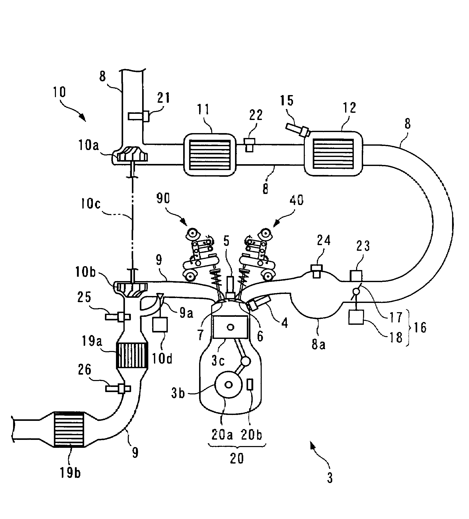
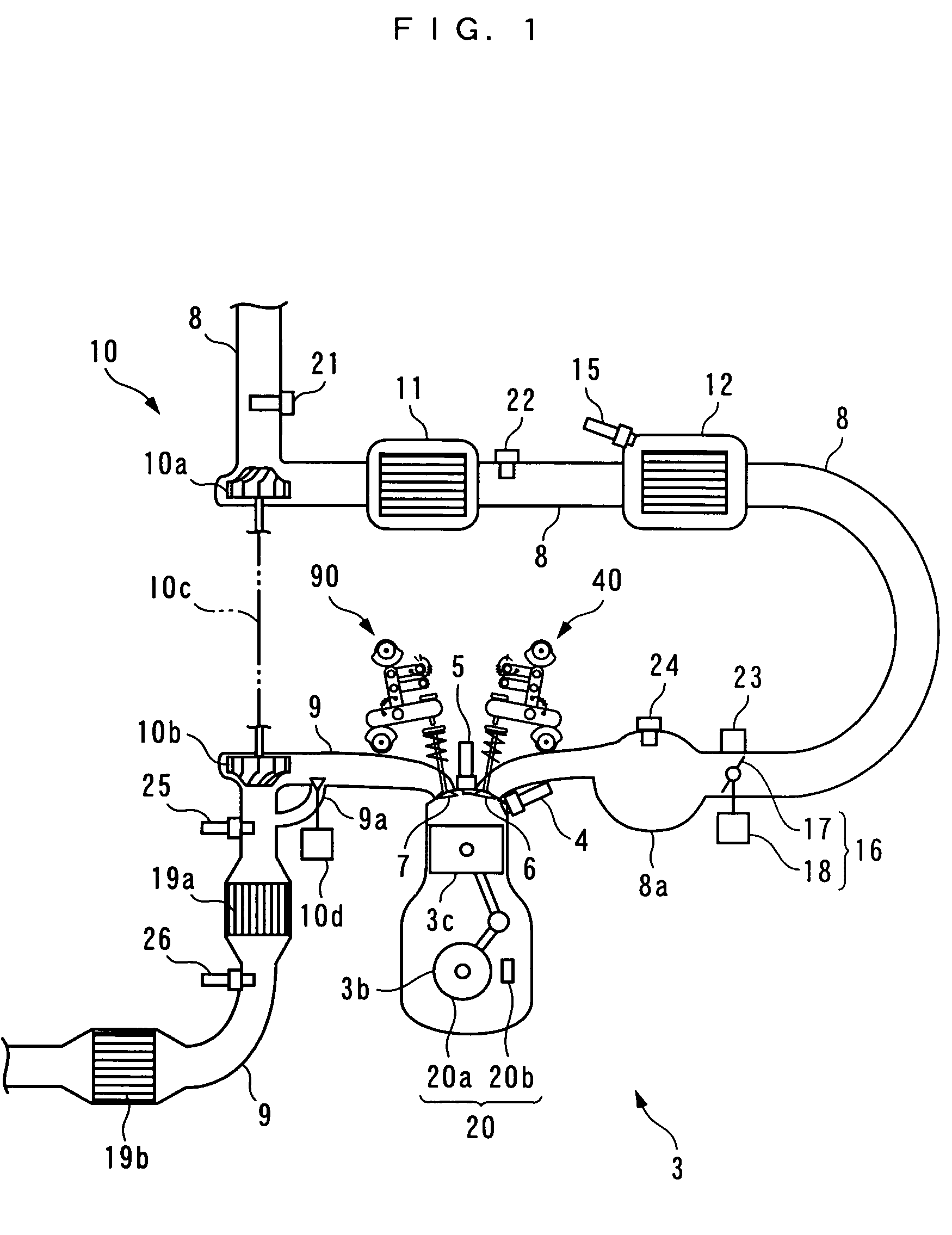
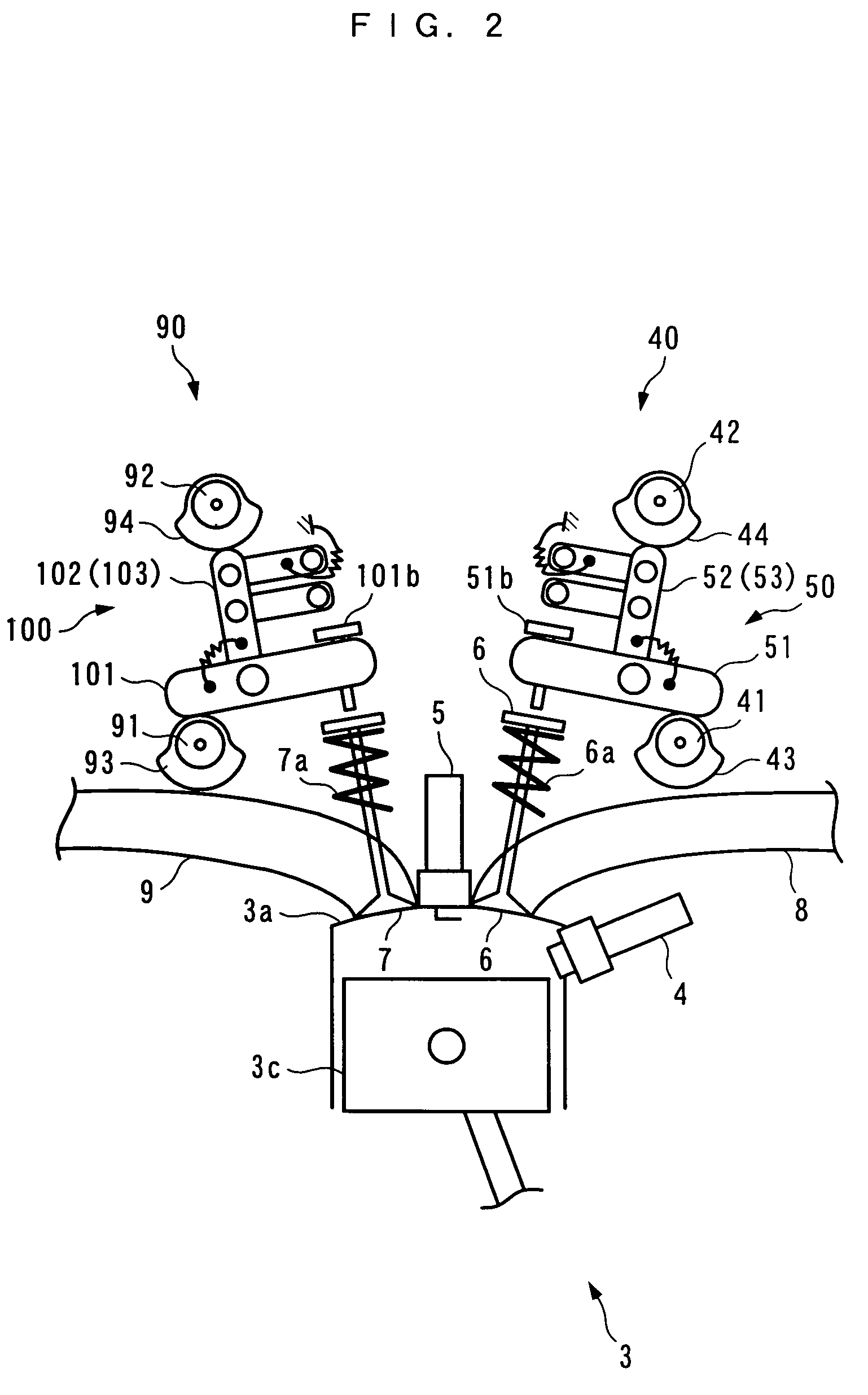
[0182]The invention will now be described in detail with reference to the drawings showing a preferred embodiment thereof. Referring first to FIGS. 1 and 2, there is schematically shown the arrangement of an internal combustion engine 3 (hereinafter simply referred to as “the engine 3”) to which is applied a control system 1 (intake air amount control system / control system) according to the present embodiment. FIG. 3 schematically shows the arrangement of the control system 1. As shown in FIG. 3, the control system 1 includes an ECU 2. The ECU 2 carries out control processes, as described hereinafter, including a process for control of valve timing of intake valves 6 and exhaust valves 7, based on operating conditions of the engine 3.

[0183]The engine 3 is an inline four-cylinder gasoline engine installed on an automotive vehicle, not shown, and has first to fourth cylinders #1 to #4 (see FIG. 5). Further, the engine 3 includes main fuel injection valves 4 (only one of which is shown...


PUM


Abstract

An intake air amount control system for an internal combustion engine, which is capable of ensuring high robustness and improving controllability in intake air amount control, to thereby improve drivability and reduce exhaust emissions. A control system of an internal combustion engine, which variably controls the amount of intake air drawn into cylinders as desired via a variable intake valve actuation assembly includes an ECU 2. The ECU 2 calculates a cylinder intake air amount Gcyl and a target intake air amount Gcyl_cmd based on a controlled object model, a vector θs of all model parameters of the controlled object model with an identification algorithm, calculates a target auxiliary intake cam phase θmsi_cmd based on the vector θs with a sliding mode control algorithm, and controls the variable intake valve actuation assembly according to the target auxiliary intake cam phase θmsi_cmd.

Description

CROSS-REFERENCE TO RELATED APPLICATION[0001]This application is a National Stage entry of International Application No. PCT / JP2004 / 007355, filed May 28, 2004, the entire specification claims and drawings of which are incorporated herewith by reference.FIELD OF THE INVENTION[0002]The present invention relates to an intake air amount control system for an internal combustion engine that changes valve timing of an intake valve to thereby change the amount of intake air drawn into the cylinder as desired, and a control system that controls a plant by determining an input to the plant with a control algorithm based on a controlled object model that defines a relationship between the input to the plant and an output from the plant.BACKGROUND ART[0003]Conventionally, an intake air amount control system for an internal combustion engine, which is described in Patent Literature 1, is known as the intake air amount control system of the above-mentioned kind. The engine has an electromagnetic ...

Claims


Application Information

Patent Timeline
Patent Type & Authority Patents(United States)
IPC IPC(8): F02D28/00G06F17/00F01L1/34F01L13/00F02B23/10F02B75/12F02D13/02F02D41/00F02D41/04F02D41/14F02D41/18F02D41/34F02D45/00G05B11/36G05B13/00G05B13/04
CPCF01L13/0047F02D13/0207F02D41/0002F02D41/008F02D41/1402F02D41/18G05B13/047F01L1/08F01L1/18F01L1/185F01L2800/00F02B23/104F02B2075/125F02D41/1403F02D2041/001F02D2041/1423F02D2041/1433F02D2200/0402Y02T10/18Y02T10/42Y02T10/12Y02T10/40
Inventor YASUI, YUJIYONEKAWA, AKIYUKI
Owner HONDA MOTOR CO LTD
Why Eureka
Try Eureka