Syringe safety device

a safety device and syringe technology, applied in the field of syringe safety devices, can solve the problems of limited broad utility of syringe-containing cartons, inconvenient operation, and inability to meet the needs of patients,

Inactive Publication Date: 2008-12-30
WEST PHARM SERVICES INC
View PDF30 Cites 58 Cited by
  • Summary
  • Abstract
  • Description
  • Claims
  • Application Information

AI Technical Summary

Benefits of technology

[0008]A syringe safety device configured to form a fluid coupling between a sealed vial and a syringe, the syringe safety device comprising: a tubular connector having opposing first and second axial open ends, the first open axial end being adapted to engage an end of a conventional medicine vial with stopper; and a sliding joint received in the second open axial end of the tubular connector, the sliding joint having opposing first and second axial ends and a passageway between the first and second axial open ends, the first axial open end being adapted to engage with an enlarged, blunt mounting end of a syringe needle, the second axial end of the sliding joint further being adapted to releasably engage at least a releasable needle receiver on a distal end of a barrel of a conventional syringe without needle, the syringe being releasably removable from the sliding joint after fluid coupling with the vial through the passageway of the sliding joint without removal of the sliding joint from the tubular connector and without the needle.

Problems solved by technology

The requirement for use with a special cartridge containing syringe limits its broad utility.
Such a mode of operation is not always convenient.
However, that is not always possible.
Agitation of the bag and vial at that can be disturbing to the patient and can sometimes result in separation of the catheter tube from the needle connecting the bag to the patient or of the catheter needle from the patient.

Method used


Image

  • Syringe safety device
  • Syringe safety device
  • Syringe safety device

Examples


Embodiment Construction

[0022]Certain terminology is used in the following description for convenience only and is not limiting. The words “right,”“left,”“lower” and “upper” designate directions in the drawings to which reference is made. The words “inwardly” and “outwardly” refer to directions toward and away from, respectively, the geometric center of the syringe safety device and designated parts thereof. The terminology includes the words above specifically mentioned, derivatives thereof, and words of similar import.

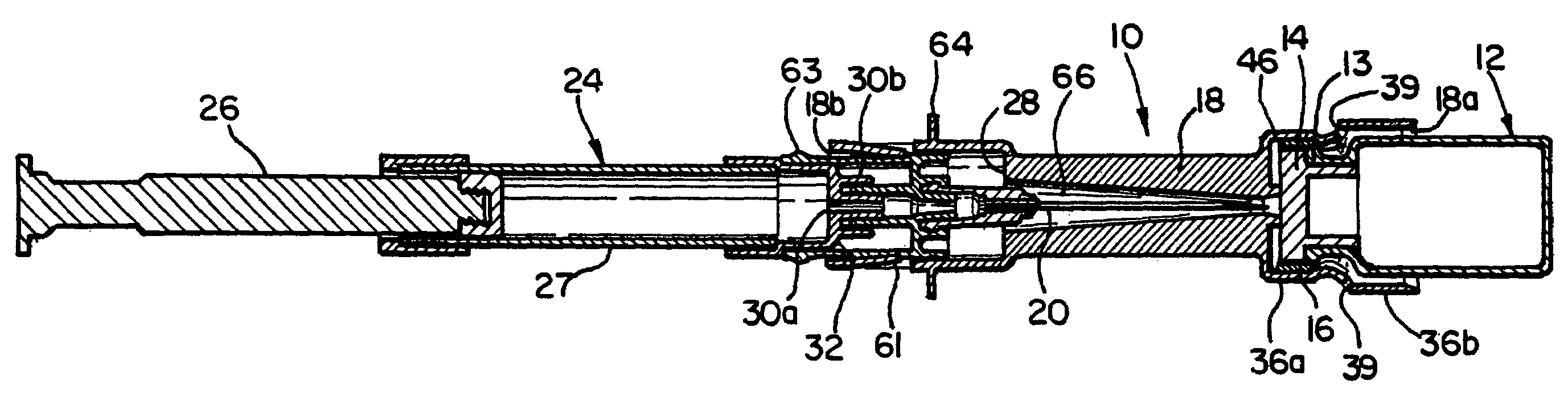
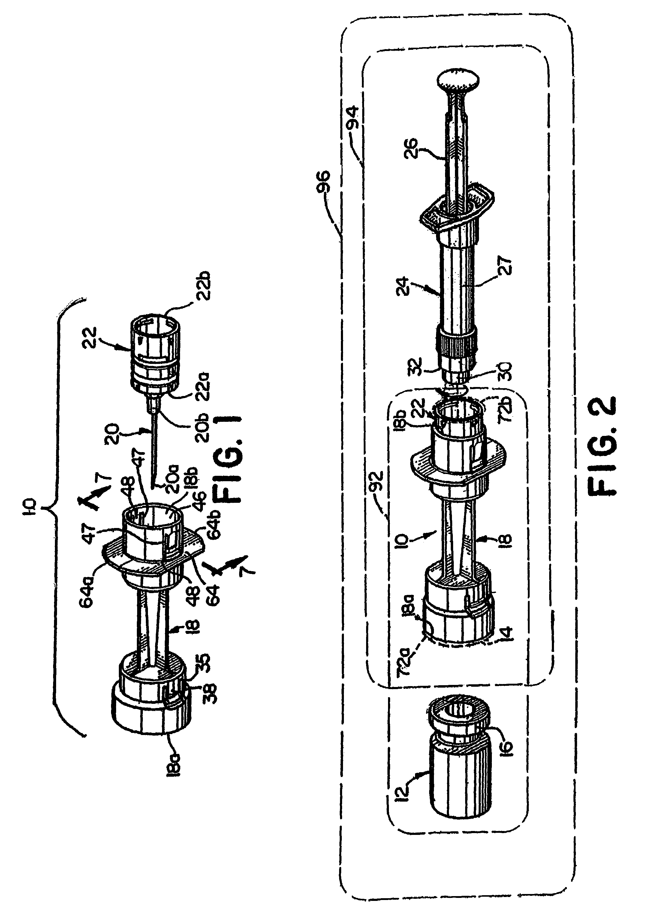
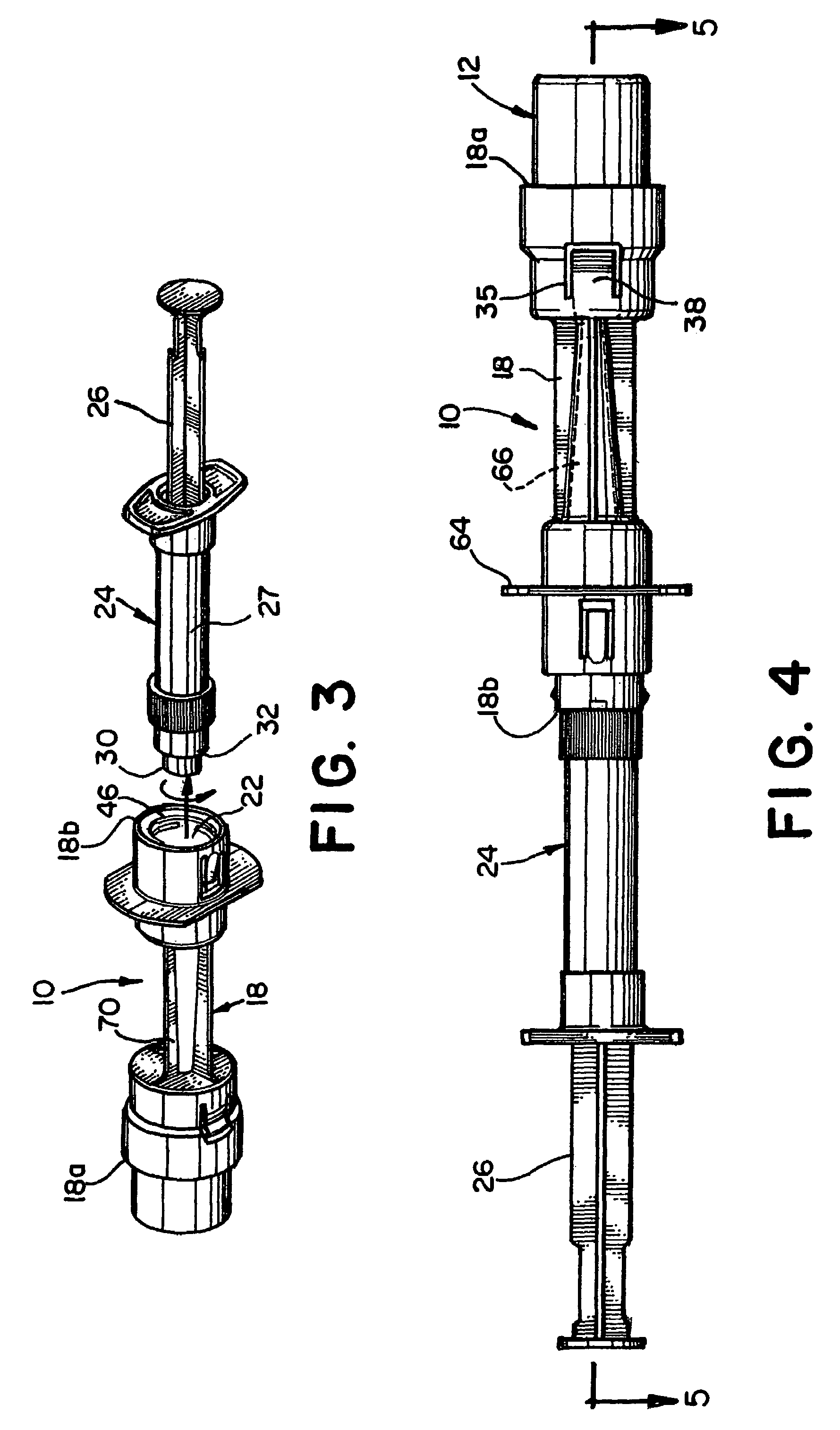
[0023]Referring to the drawings in detail wherein like numerals represent like elements throughout, FIGS. 1-6 illustrate a syringe safety device according to the present invention, generally designated at 10. Briefly stated, the syringe safety device 10 of the present invention allows a user to reconstitute medicine, or withdraw fluid from a stoppered vial 12, without exposing the user to any potential needle sticks. The syringe safety device 10 allows a user to inject the contents of a syr...


PUM

PropertyMeasurementUnit
diameteraaaaaaaaaa
flexibleaaaaaaaaaa
relative rotational movementaaaaaaaaaa

Abstract

A syringe safety device coupling between a vial and a syringe, including a tubular connector having a first axial end receiving the vial and a second, opposing axial end releasably receiving a syringe. The tubular connector encloses a sliding joint having opposing open axial ends and a passageway between the ends. A first sliding joint end is adapted to engage a syringe needle. A second sliding joint end is configured to releasably engage a needle receiver. The syringe is releasably removable from the sliding joint after fluid coupling with the vial through the sliding joint, without removal of the needle or the sliding joint from the connector, which captures the needle with the sliding joint in the connector. The first end of a joint includes a receiver, adapted to releasably receive a removable syringe needle, and a mount, adapted to releasably receive a releasable needle receiver of a syringe.

Description

CROSS-REFERENCE TO RELATED APPLICATIONS[0001]This patent application is a continuation of U.S. patent application Ser. No. 10 / 011,262, filed Nov. 7, 2001 now U.S. Pat. No. 6,729,370, which claims priority to U.S. Provisional Patent Application No. 60 / 246,635, filed Nov. 8, 2000, entitled “Syringe Safety Device,” the subject matter of which is incorporated herein by reference.BACKGROUND OF THE INVENTION[0002]This invention is directed to a syringe safety device and, more specifically, to a syringe device that allows a user to reconstitute medicine in sealed vials without risk of the user being stuck by a needle needed to access the contents of the vial. It is often desirable to store drugs in a concentrated or powdered (e.g., lyophilized) form until just prior to administering the drug to a patient at which time the medicine is mixed with a solvent of diluent or rehydrant. Several different arrangements for mixing such drugs and liquids have been disclosed.[0003]U.S. Pat. No. 5,653,6...

Claims


Application Information

Patent Timeline
Patent Type & Authority Patents(United States)
IPC IPC(8): A61M5/00A61M5/32A61J1/00A61J1/20
CPCA61J1/2096A61J2001/201A61J2001/2051A61J2001/2065A61J1/201A61J1/2051A61J1/2065
Inventor NORTON, PAUL H.WOLFE, JOHN R.
Owner WEST PHARM SERVICES INC
Why Eureka
Try Eureka