Rubbing angle-measuring equipment, and manufacturing methods of liquid crystal display device and optical film

a technology of liquid crystal display device and manufacturing method, which is applied in the direction of optical radiation measurement, instruments, navigation instruments, etc., can solve the problems of difficult to conduct measurement just after rubbing or feeding, and difficulty in controlling the rubbing angle at an accuracy of 0.2° or higher, and achieve stable optical characteristics and high accuracy.

Active Publication Date: 2008-12-30
JAPAN DISPLAY INC +1
View PDF4 Cites 9 Cited by
  • Summary
  • Abstract
  • Description
  • Claims
  • Application Information

AI Technical Summary

Benefits of technology

[0044]According to the rubbing angle measuring equipment of the invention, by imaging the surface of a substrate or a film after rubbing under Crossed Nichols in a liquid crystal panel or an optical film for which rubbing is conducted in the manufacturing process, rubbing angle thereof can be measured at a high accuracy. Therefore, it is possible to conduct measurement just after rubbing, to feed back the result of the rubbing angle measurement instantly to the rubbing condition or feed forward the result to the condition in the subsequent process such as cutting or overlapping. This enables rubbing at an optimal angle and cutting or overlapping of a base material (film or substrate) conforming the rubbing angle, making it possible to manufacture a liquid crystal panel or the manufacture of an optical film having stable optical characteristics.

Problems solved by technology

In a rubbing process as one of manufacturing processes of a liquid crystal panel or an optical film, even when a fabrication accuracy of a rubbing machine is improved, it is difficult to control the rubbing angle at an accuracy of 0.2° or higher by dispersion of rubbing conditions attributable to a rubbing cloth such as cloth grain.
Further, along with enlarging scale of substrates handled in the liquid crystal panel manufacturing process in recent years, in-plane distribution of the rubbing angle due to dispersion of the rubbing cloth has caused a significant problem and the control for the rubbing angle has become an important subject.
Accordingly, it was difficult to conduct measurement just after rubbing or feed back the result of the measurement instantly to a rubbing process.

Method used


Image

  • Rubbing angle-measuring equipment, and manufacturing methods of liquid crystal display device and optical film
  • Rubbing angle-measuring equipment, and manufacturing methods of liquid crystal display device and optical film
  • Rubbing angle-measuring equipment, and manufacturing methods of liquid crystal display device and optical film

Examples


embodiment 1

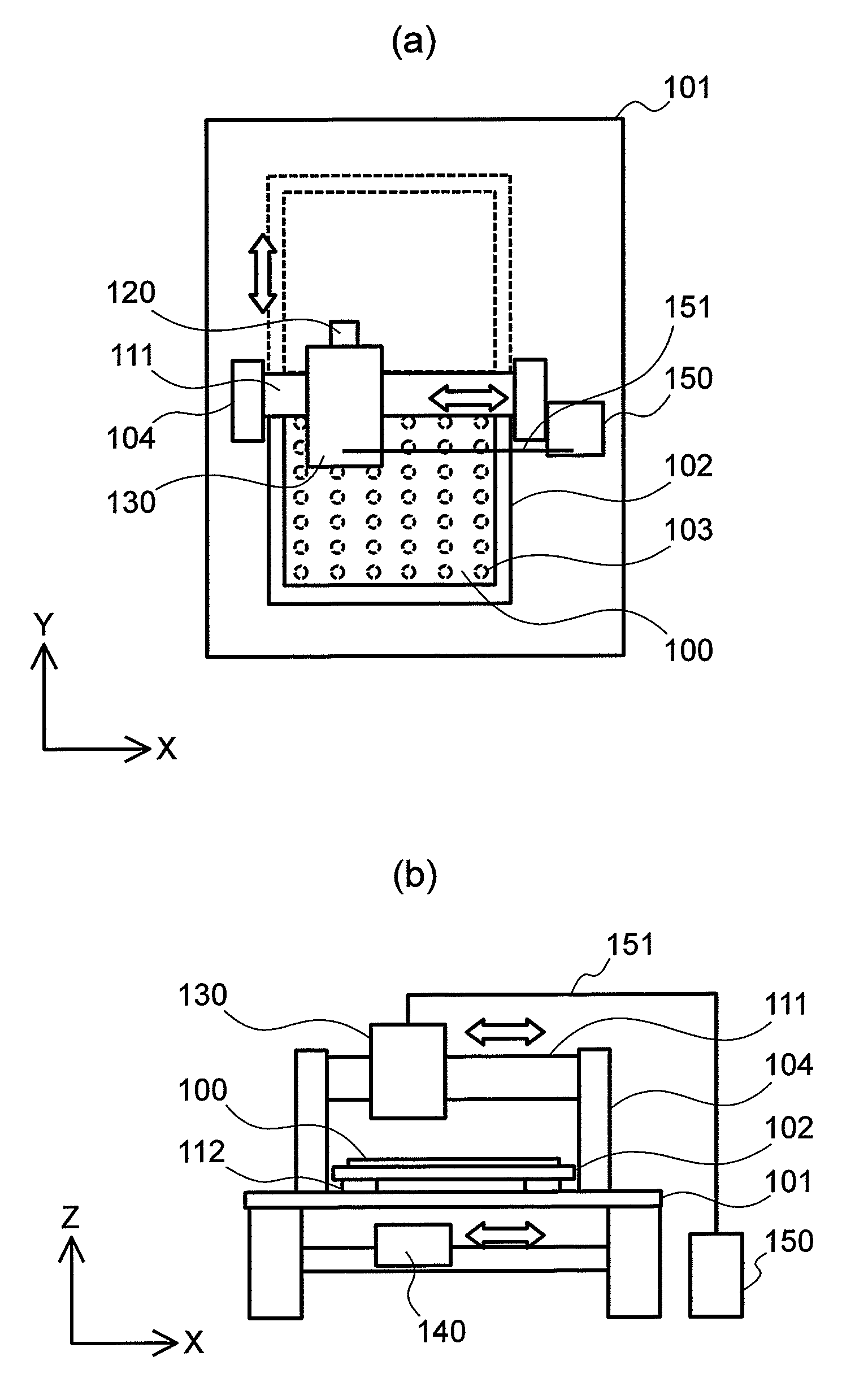
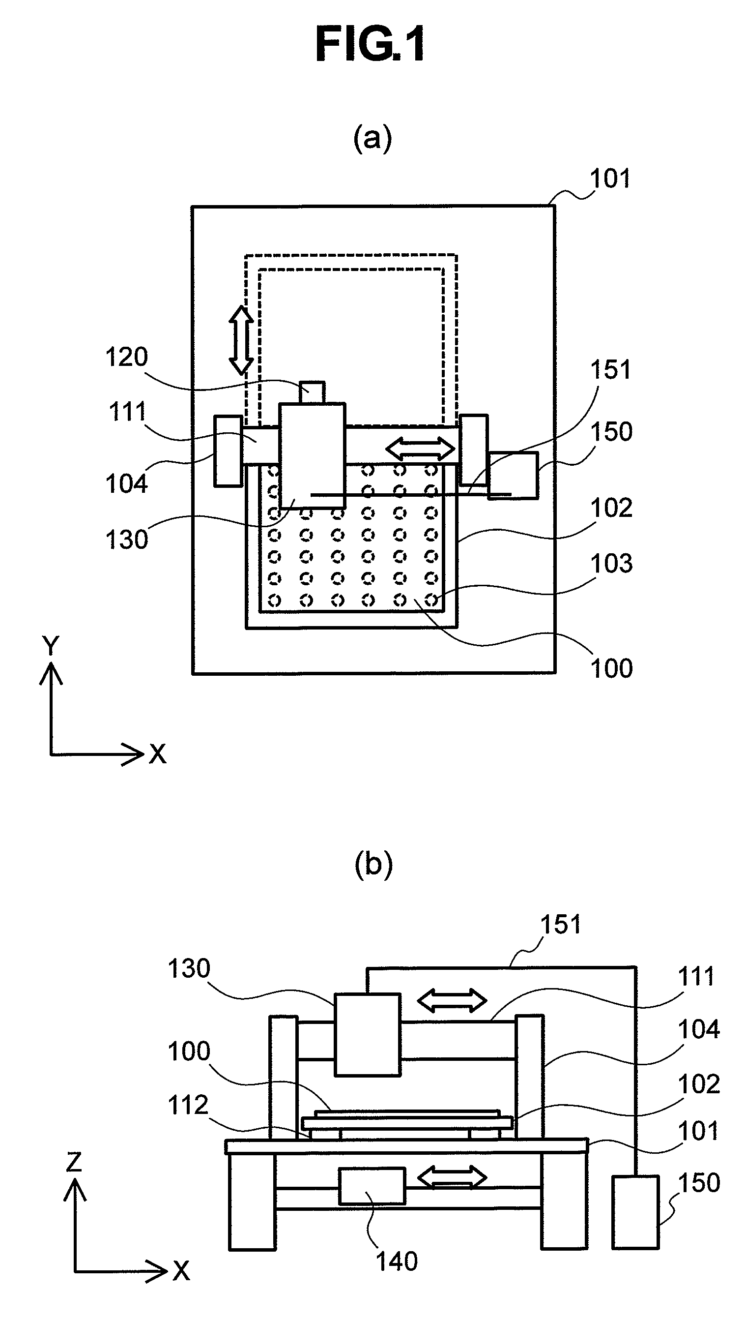
[0061]FIG. 1 shows a rubbing angle measuring equipment according to a first embodiment of the invention. FIG. 1(a) shows a plan view of a rubbing angle measuring equipment according to the embodiment. In the rubbing angle measuring equipment of this embodiment, an imaging unit 130, an imaging unit moving mechanism 111, and an imaging unit moving mechanism support 104 are provided on a surface table 101. The imaging unit 130 has a structure of holding a mark or end detection camera 120 on the lateral side. Further, a stage 102 for holding a measuring object 100 rubbed at the surface for alignment of liquid crystals is provided on a stage moving mechanism 112 (refer to FIG. 1 (b). The stage moving mechanism 112 is provided on the surface table 101. An orthogonal coordinate system shown in FIG. 1(a) is shown, for example, as an X-Y plane within the plane (an upper surface) of the surface table 101.

[0062]FIG. 1(b) shows a side elevational view of a rubbing angle measuring equipment of t...

example 2

[0077]FIG. 7 shows an example of a manufacturing process for a liquid crystal panel. The manufacturing process for the liquid crystal panel includes an alignment film forming process 703 of coating a polymeric solution such as of a polyimide to a CF substrate 701 and a TFT substrate 702 by a flexographic printing press 711 and calcining in a calcination furnace 712, a rubbing process 704 of rotating a rubbing roller 713 which is wound around with a rubbing cloth at a high speed to rub the surface of an alignment film to apply anchoring energy to respective substrates, an overlapping step 705 of opposing and overlapping the processed surfaces of the CF substrate 701 and the TFT substrate 702 such that the rubbing directions are in inverse parallel, a cutting step 706 of dividing the same into a multi-facetted panel size, and a liquid crystal sealing process 707 of sealing liquid crystals 714. While the CF substrate 701 and the TFT substrate 702 were used, a glass substrate not provid...

embodiment 3

[0081]FIG. 9 shows an outline of a rubbing angle measuring equipment as a third embodiment of the invention. FIG. 9(a) is an X-Y plane view of a rubbing angle measuring equipment according to the invention, FIG. 9(b) is an XZ plan view and FIG. 9(c) is a YZ plan view. The rubbing angle measuring equipment of this embodiment is designed for an elongate measuring matter such as an optical film as an object. The equipment includes a light source unit 901, an illumination optical unit support 910, an imaging unit 903, a laser irradiation unit 907, a signal transmission line 904, and an image evaluation means 906. A line sensor at high sensitivity is used for the imaging means of the imaging unit 903 and the imaging means operates at a frequency in synchronization with a winding speed of an elongate measuring object 902 to obtain an image on the surface of the measuring object 902. A measuring light derived from the light source unit 901 passes the measuring object 902 and enters the ima...


PUM


Abstract

A rubbing angle measuring equipment of the invention includes an light source unit, a measuring optical system, an imaging means, and an image evaluation means in which the measuring optical system is adapted such that a light from the light source unit passes by way of an illumination optical system and a polarizer to a rubbed measuring object and further passes by way of an analyzer and a focusing optical system to the imaging means, and the surface of the measuring object is focused to the imaging means, and in which image signals obtained by the imaging means are transmitted to the image evaluation means where signals having an intense periodicity in the image are detected, to measure the rubbing angle of the measuring object in a nondestructive manner, within a short period and at a high accuracy of 0.1° or more.

Description

[0001]The present application claims priority from Japanese application JP2006-105822 filed on Apr. 7, 2006, the content of which is hereby incorporated by reference into this application.BACKGROUND OF THE INVENTION[0002]1. Field of the Invention[0003]The present invention concerns an apparatus for nondestructive measurement of a rubbing angle (alignment control direction) in a substrate just after a rubbing treatment of the substrate, as well as manufacturing methods of a liquid crystal display device and an optical film using a substrate controlled for the rubbing angle by the measurement.[0004]2. Description of the Related Art[0005]FIG. 12 schematically shows the structure of an IPS (in-plane switching) type liquid crystal display device as an example of a liquid crystal display device. An unpolarized light emitted from a backlight 1241 passes through a lower polarizer plate 1231 and is polarized. The polarized light passes a liquid crystal panel 1211 and, further, passes an uppe...

Claims


Application Information

Patent Timeline
Patent Type & Authority Patents(United States)
IPC IPC(8): G01B11/26
CPCG01N21/21G01N2021/218G01N2021/9513G02F1/133784
Inventor KISHIOKA, ATSUSHI
Owner JAPAN DISPLAY INC
Why Eureka
Try Eureka