Solid electrolytic capacitors

a technology of electrolyte capacitors and solid electrolyte, which is applied in the manufacture of electrolyte capacitors, liquid electrolytic capacitors, capacitor dielectric layers, etc., can solve the problems of significant current leakage, failure of weak adhesion between the electrolyte layer and the dielectric layer

Inactive Publication Date: 2008-12-30
ACULON +1
View PDF10 Cites 41 Cited by
  • Summary
  • Abstract
  • Description
  • Claims
  • Application Information

AI Technical Summary

Problems solved by technology

Significant current leakage can result if the adhesion between the electrolyte layer and the dielectric layer fails.
If the capacitor is subjected to external stresses, the adhesion between these layers may suffer, and the series resistance can increase.

Method used


Image

  • Solid electrolytic capacitors
  • Solid electrolytic capacitors
  • Solid electrolytic capacitors

Examples


Embodiment Construction

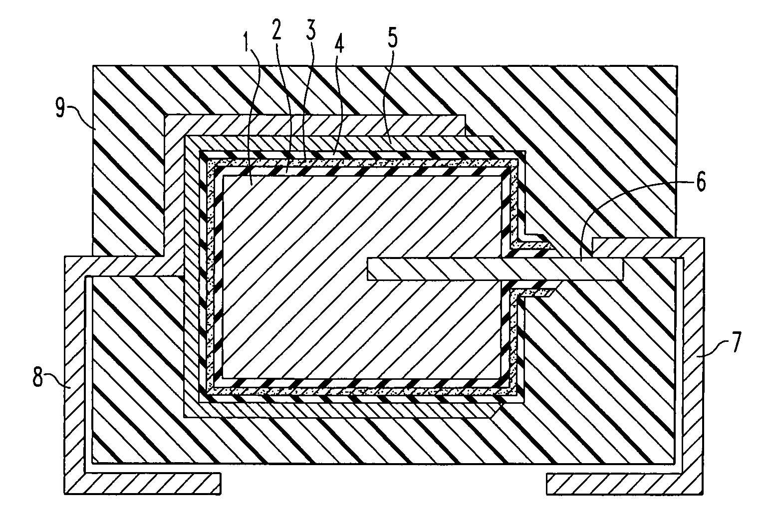
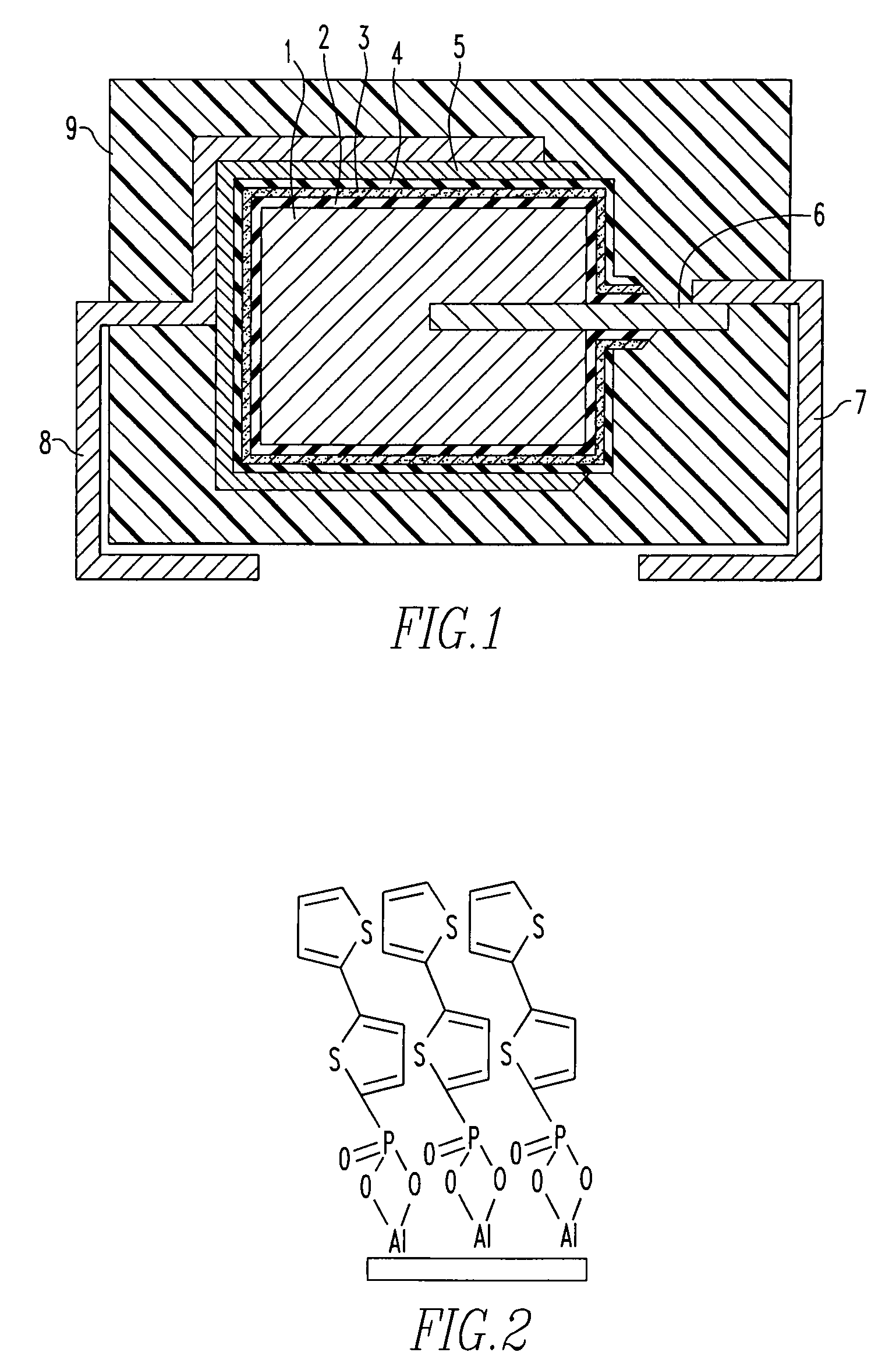
[0014]Referring to FIG. 1 the capacitor comprises an anode 1 which may be a sintered valve metal such as aluminum, tantalum, niobium, silicon and titanium and a dielectric coating 2 typically formed by oxidation of the anode material, that is, an oxide of aluminum, tantalum or niobium.

[0015]The capacitor comprises an electrolyte layer 4 and a cathode layer typically a graphite-silver paste layer 5. Positioned between the electrolyte layer 4 and the dielectric layer 2 is a layer of an organophosphorus material 3. An anode terminal 7 is connected to the anode lead member 6 inserted into the anode body 1 from one end surface thereof. A cathode terminal 8 is connected to the cathode layer 5 and the capacitor is sealed with an exterior resin 9 such as an epoxy or a phenolic resin.

[0016]The electrolyte layer 3 is formed from an electrically conductive (includes semi conductive) polymer. Examples of electrically conductive polymers are π conjugated polymers such as polyaniline, polythiophe...


PUM

PropertyMeasurementUnit
wavelengthaaaaaaaaaa
temperatureaaaaaaaaaa
conductiveaaaaaaaaaa

Abstract

A solid electrolytic capacitor is disclosed. The capacitor comprises an organophosphorus material positioned between the dielectric layer and the polymeric electrolyte layer. The organophosphorus compound improves the interlayer adhesion between the dielectric and electrolyte layers.

Description

CROSS REFERENCE TO RELATED APPLICATION[0001]The present application claims priority from U.S. Provisional Patent Application Ser. No. 60 / 788,290, filed Mar. 31, 2006.FIELD OF THE INVENTION[0002]The present invention relates to solid electrolytic capacitors comprising a conductive polymer layer bonded to a dielectric layer, and more particularly, to solid electrolytic capacitors having improved adhesion between the conductive polymer layer and the dielectric layer.BACKGROUND OF THE INVENTION[0003]A solid electrolytic capacitor consists of a valve metal anode, a dielectric layer that is usually an oxide of the valve metal, an electrolyte layer that is typically formed from a conductive polymer and is positioned over the dielectric layer. A cathode layer is positioned over the electrolyte layer and the structure is encapsulated in a dielectric plastic.[0004]For optimum usage, the electrolytic capacitor must have low current leakage and be resistant to external stresses. Significant cur...

Claims


Application Information

Patent Timeline
Patent Type & Authority Patents(United States)
IPC IPC(8): H01G9/02H01G9/04
CPCH01G9/0036H01G9/042H01G9/07H01G9/15H01G11/56Y02E60/13
Inventor BRUNER, ERIC L.MERKER, UDO
Owner ACULON
Why Eureka
Try Eureka