Combined cooling and power plant with water extraction

a technology of power plant and water extraction, which is applied in the direction of machines/engines, mechanical equipment, light and heating equipment, etc., can solve the problems of increasing the number of applications, increasing the cost of additional system complexity and cost, and increasing the cost, size, and weight of the system, so as to increase the efficiency of the turbine engine

a technology of power plant and water extraction, which is applied in the direction of machines/engines, mechanical equipment, light and heating equipment, etc., can solve the problems of increasing the number of applications, increasing the cost of additional system complexity and cost, and increasing the cost, size, and weight of the system, so as to increase the efficiency of the turbine engine

US7472550B2Inactive Publication Date: 2009-01-06UNIV OF FLORIDA RES FOUNDATION INC

Image

  • Combined cooling and power plant with water extraction
  • Combined cooling and power plant with water extraction
  • Combined cooling and power plant with water extraction

Examples


example 1

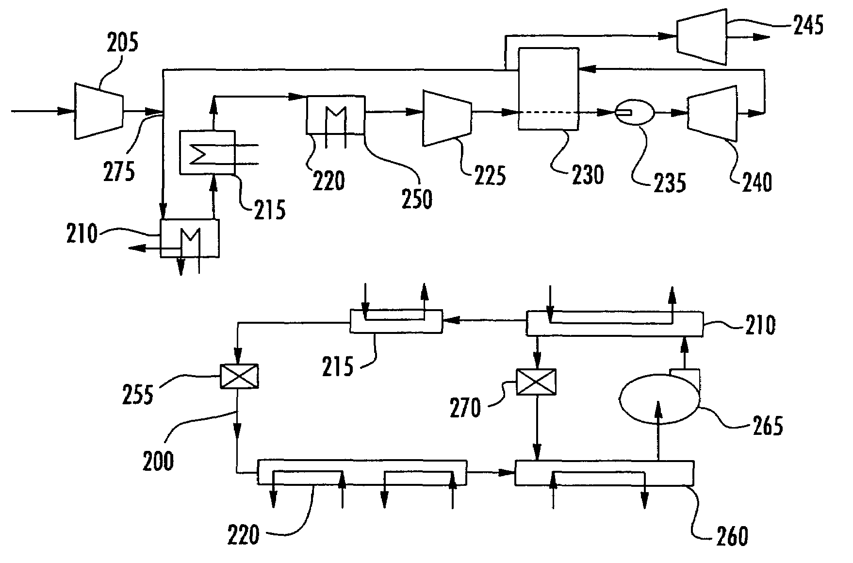
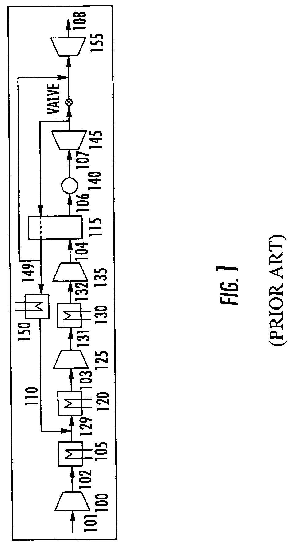
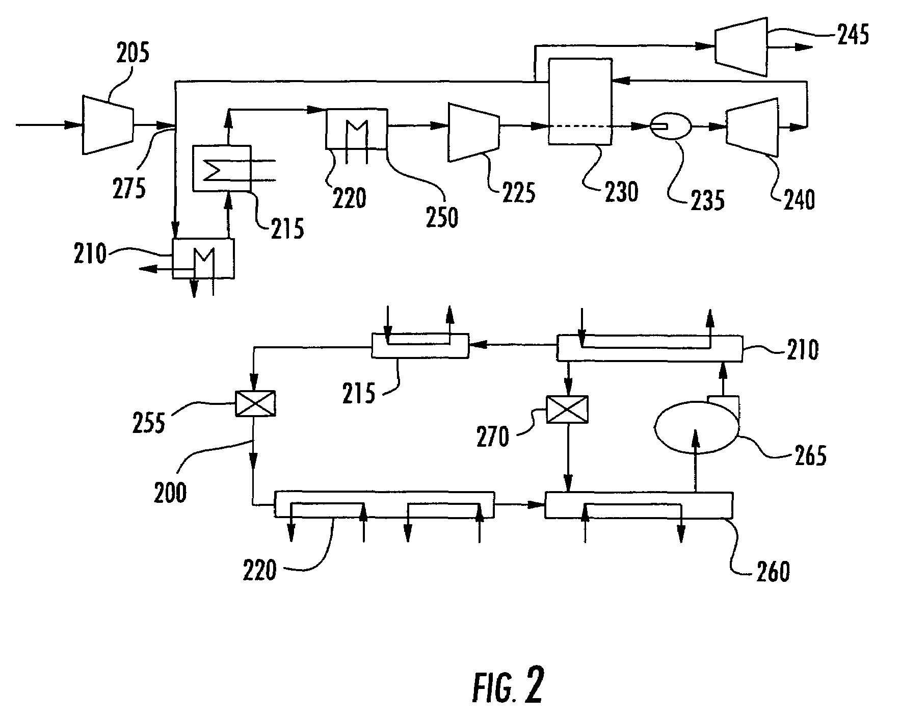
[0037]The cycle configuration for this example includes a combined gas-turbine absorption refrigeration cycle as shown in FIG. 4. The gas-turbine portion is the HPRTE that is shown in FIG. 1. The absorption refrigeration portion is an ammonia / water single-stage system. The generator 410 was placed after the mixing junction of the recirculated exhaust and the incoming air in the gas turbine cycle. The evaporator 420 of the system was placed after the condenser 415 and heat exchanger 418 and water was extracted in the evaporator 420. Also, evaporator temperatures were constrained to be above the freezing point of water due to the large amount of water vapor in the hot gas stream in contact with the evaporator 420. The system also included a second heat exchanger 423 and expanding 455 and regulating 470 valves.

[0038]The cycle code was written in FORTRAN to include all of the heat exchangers shown, but in the cases presented in this example 105, 130, and 150 were turned off. 105 and 150...


PUM


Abstract

A turbine engine system and a method for using the turbine engine system that includes at least one low-pressure compressor, at least one high-pressure compressor, at least one low-pressure turbine, and at least one high-pressure turbine. In addition, the turbine engine system includes an absorption refrigeration system that is used to pre-cool an air-gas mixture before it enters the high-pressure compressor. As such, the pre-cooled mixture is easier to compress, thereby increasing the thermal efficiency of the turbine engine. Additionally, the exhaust heat from the air-gas mixture that is pre-cooled may be used to drive the absorption refrigeration system. Lastly, water, may be extracted from the evaporator of the absorption refrigeration cycle.

Description

CROSS-REFERENCE TO RELATED APPLICATIONS[0001]This application claims priority to U.S. Provisional Patent Application No. 60 / 579,205, which was filed Jun. 14, 2004.STATEMENT REGARDING FEDERALLY SPONSORED RESEARCH OR DEVELOPMENT[0002]The United States Government has rights in this invention pursuant to Grant No. 58-3148-3-069 between the United States Department of Agriculture and the University of Florida.FIELD OF THE INVENTION[0003]The invention relates to combined cycle engines. More specifically, the invention relates to a gas turbine regenerative engine.BACKGROUND OF THE INVENTION[0004]There are many variations on simple cycle gas turbines, which can provide features such as small size, light in weight, reliability, simplicity, or other attributes. Emphasis is often placed on performance and power density, and achieving these objectives through use of known technologies and design principles for compressors, turbines, combustors, heat exchangers, and technology from related conve...

Claims


Application Information

Patent Timeline
06 Jan 2009
Publication
US7472550B2
IPC
F02C1/00; F02G3/00
CPC
F01D15/005; F02C1/08; F02C3/34; F02C7/08; F02C7/143; Y02T50/676; F05D2260/211; F05D2260/232
Inventors
LEAR, JR., WILLIAM E.; SHERIF, SHERIF A.