Fuel injection system
a fuel injection and system technology, applied in the direction of fuel injection apparatus, charge feed system, electric control, etc., can solve the problems of deviation in actual injection timing, imposing a very heavy operational load on the controller, and affecting the operation of the controller
- Summary
- Abstract
- Description
- Claims
- Application Information
AI Technical Summary
Benefits of technology
Problems solved by technology
Method used
Image
Examples
first embodiment
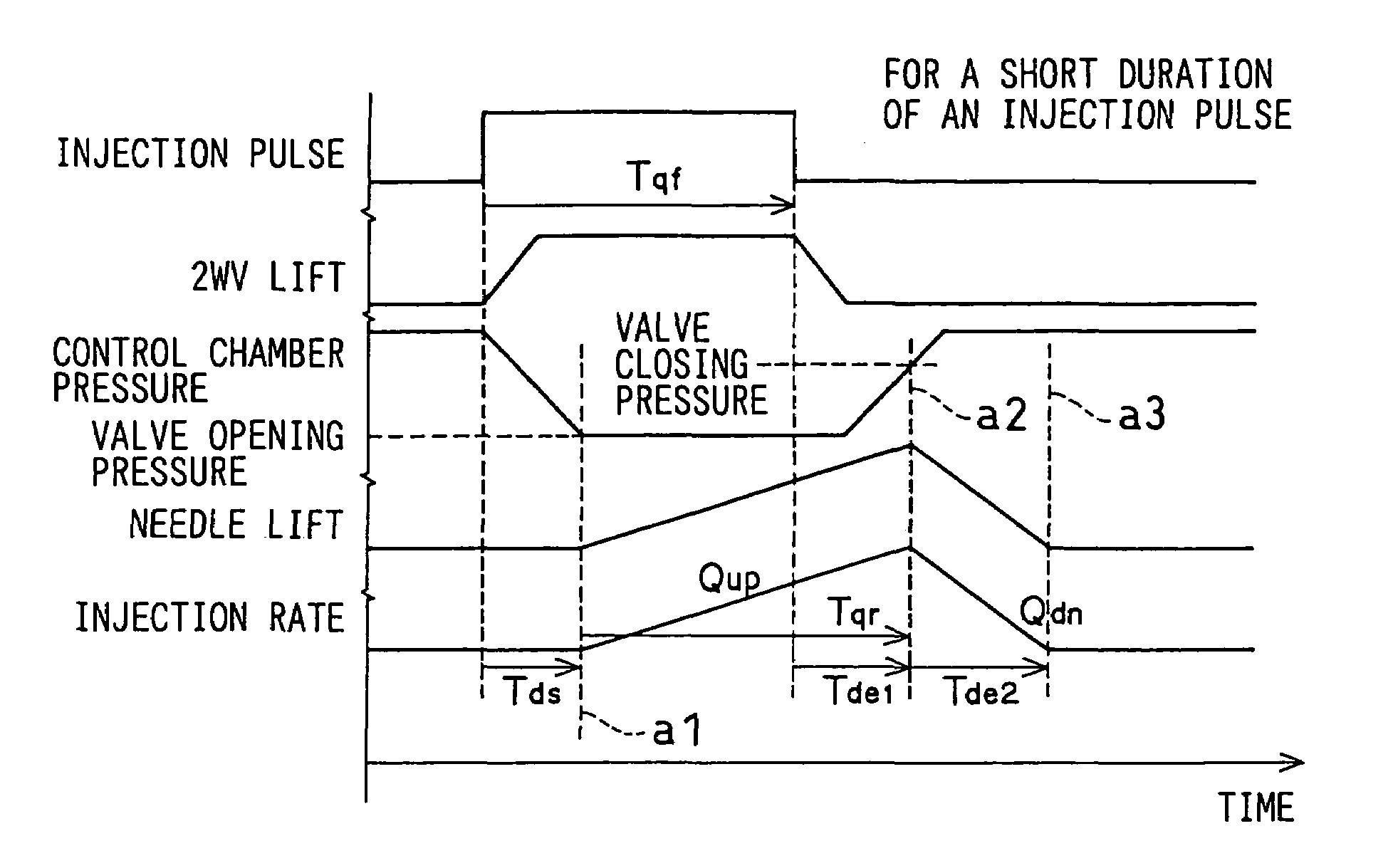
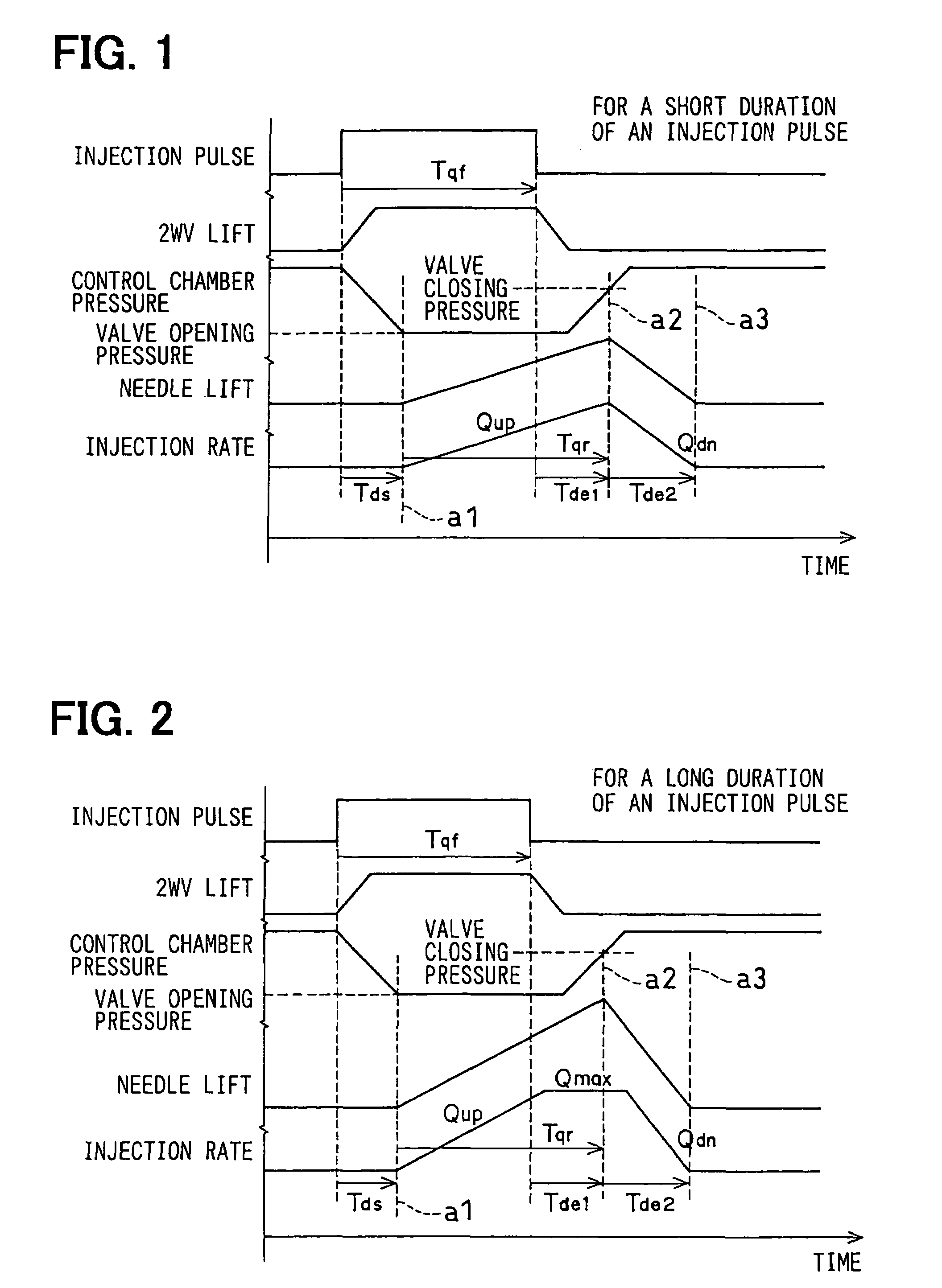
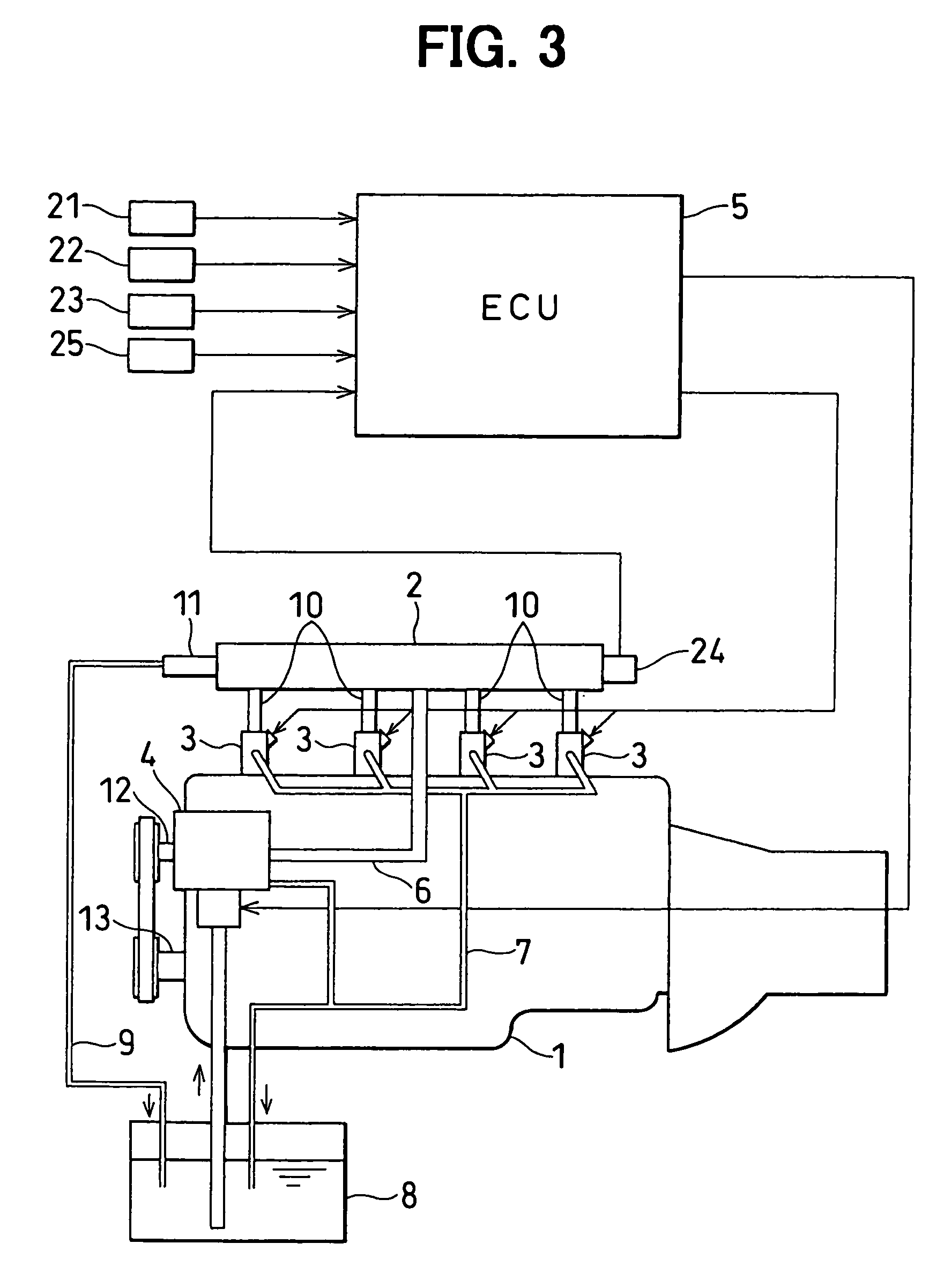
[0035]Now, reference is made to FIGS. 1 to 4 to explain the first embodiment of the present invention, which is applied to a common rail fuel injection system. First, the configuration of the common rail fuel injection system will be explained with reference to FIG. 3. As an example, the common rail fuel injection system is designed to inject fuel into a diesel engine (hereinafter referred to as an engine) 1, and includes a common rail 2, injectors 3, a supply pump 4, and an ECU 5 (abbreviated as Engine Control Unit, corresponding to a controller). The engine 1 has a multiple number of cylinders, each of which experiences an intake, compression, combustion, and exhaust stroke. As an example, FIG. 3 shows a four-cylinder engine, however, the present invention is also applicable to an engine having a different number of cylinders.
[0036]The common rail 2 is an accumulator vessel for accumulating high-pressure fuel to be supplied to the injector 3. The common rail 2 is connected to the ...
second embodiment
[0076]In the first embodiment above, such an example was shown in which the rising injection rate Qup, the falling injection rate Qdn, and the maximum injection rate Qmax were directly determined, which were then used to determine the geometry of the injection rate. The example was also adapted such that the rising injection rate Qup, the falling injection rate Qdn, and the maximum injection rate Qmax were determined using the function or map based on the injector supply pressure (the common rail pressure Pc) and the specification of the injector 3. That is, in the first embodiment above, such an example was shown in which the geometry of the injection rate was directly determined using the function or map based on the injector supply pressure (the common rail pressure Pc) and the specification of the injector 3.
[0077]In contrast to this, in the second embodiment, a geometry defined by a change in needle lift quantity with respect to time is first determined, and then the geometry o...
third embodiment
[0081]The ECU 5 is provided with a correction function for changing the quantity of injection (e.g., a function for correcting for variations between the cylinders) to eliminate a variation in revolutions per minute of the engine when the RPM sensor 22 or the like detects the variation. More specifically, when a variation is detected in the revolutions per minute of the engine, correction is made to the ECU 5 to change the quantity of injection to eliminate the variation. To this end, used as an adjustment parameter is at least one of the injection parameters (for preparing the geometry of the injection rate) consisting of the valve opening pressure achieving time Tds, the rising injection rate Qup, the falling injection rate Qdn, the maximum injection rate Qmax, the valve closing pressure achieving time Tde1, the needle rise time Tqr, and the injection pulse duration Tqf. Then, the correction value of the adjustment parameter is stored as a learned value to reflect the value on the...
PUM
 Abstract
Description
Claims
Application Information
 - R&D
- Intellectual Property
- Life Sciences
- Materials
- Tech Scout
- Unparalleled Data Quality
- Higher Quality Content
- 60% Fewer Hallucinations
Browse by: Latest US Patents, China's latest patents, Technical Efficacy Thesaurus, Application Domain, Technology Topic, Popular Technical Reports.
© 2025 PatSnap. All rights reserved.Legal|Privacy policy|Modern Slavery Act Transparency Statement|Sitemap|About US| Contact US: help@patsnap.com


