Conveyor feeder house chain slat

a conveyor and feeder technology, applied in the field of conveyors and chain and slat conveyors, can solve the problems of increasing failures and wear, slow or stop processing, and subsequent loss of lubrication, so as to increase crop processing efficiency, reduce wear and breakage, and increase structure and rigidity

Active Publication Date: 2009-01-06
DEERE & CO
View PDF19 Cites 28 Cited by
  • Summary
  • Abstract
  • Description
  • Claims
  • Application Information

AI Technical Summary

Benefits of technology

[0005]Accordingly, it is an object of the present invention to provide an improved conveyor slat for a chain-and-slat type conveyor for feeding a crop in a harvesting machine such as a combine. More specifically, the improved conveyor slat comprises two “U-shaped” sections having the base of the U-shapes joined together along substantially the entire length. The shape of the slat provides for increased structure and rigidity over prior art slats, increasing crop-processing efficiency and reducing wear and breakage. One U-shaped section is longer than the other section, the longer piece being of a sufficient length that the feeder chains ride on the base, or back, of that extended U-shape, rather than on the feeder house floor, which reduces friction on the chain, which can lead to heating and consequent loss of lubrication, along with increased failures and wear. Additionally, the slats are bolted to the chain, rather than being riveted to the chain, making it easier to replace an individual slat if it should become worn or damaged. The ends of both U-shaped sections are tapered to reduce crop material wrapping around the edges thereof or the drum, which can also slow or stop processing, necessitating the combine be turned off and the clog cleared. In some arrangements of the present invention, the leading outer edge of the longer U-shaped section is serrated on the top to better pick up and pull in crop material being fed into the feeder. This improved processing of material reduces back-up of crop material from the header back into the feeder housing.

Problems solved by technology

One U-shaped section is longer than the other section, the longer piece being of a sufficient length that the feeder chains ride on the base, or back, of that extended U-shape, rather than on the feeder house floor, which reduces friction on the chain, which can lead to heating and consequent loss of lubrication, along with increased failures and wear.
The ends of both U-shaped sections are tapered to reduce crop material wrapping around the edges thereof or the drum, which can also slow or stop processing, necessitating the combine be turned off and the clog cleared.

Method used


Image

  • Conveyor feeder house chain slat
  • Conveyor feeder house chain slat
  • Conveyor feeder house chain slat

Examples


Embodiment Construction

[0010]In the discussion of the FIGURES the same reference numerals will be used throughout to refer to the same or similar components. In the interest of conciseness, various other components known to the art, such as crops, storage mechanisms and the like necessary for the operation of the invention, have not been shown or discussed, or are shown in block form.

[0011]In the following, numerous specific details are set forth to provide a thorough understanding of the present invention. However, it will be obvious to those skilled in the art that the present invention may be practiced without such specific details. Additionally, for the most part, details concerning harvester combine operation and the like have been omitted inasmuch as such details are not considered necessary to obtain a complete understanding of the present invention, and are considered to be within the knowledge of persons of ordinary skill in the relevant art.

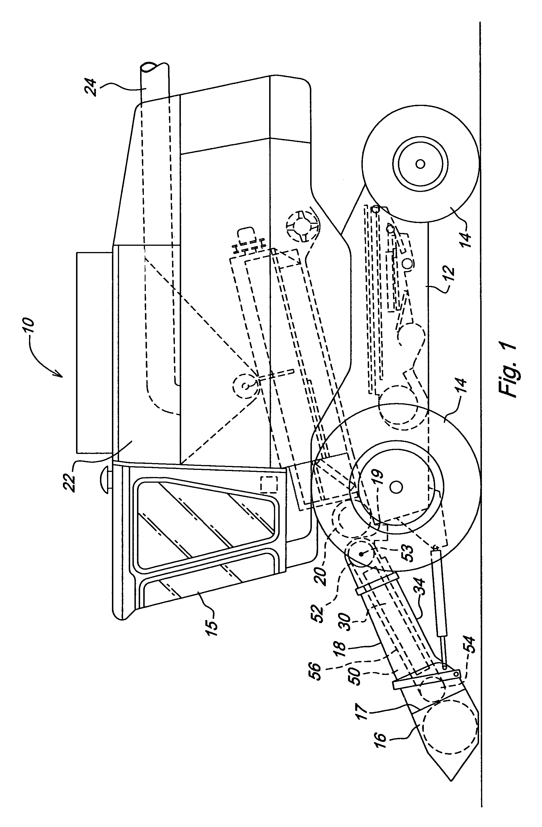
[0012]FIG. 1 shows a combine 10 used for harvesting agr...


PUM


Abstract

A new and improved conveyor feeder house chain slat having a unique shape and structure that provides sufficient structural rigidity to improve crop throughput while reducing clogging of crop material. The unique slat also provides additional support to the chain. Because the chain rides on the rear of the elongated section of the slat, the slat contacts the feed house, rather than the chain, reducing chain wear, overheating and lubricant evacuation. Because of the new slat configuration, the slats can be secured to the chain with removable securing means, enabling easier replacement of an individual slat if necessary.

Description

CROSS REFERENCE TO RELATED APPLICATION[0001]This application claims priority to provisional U.S. Patent Application 60 / 721,326 filed Sep. 28, 2005, titled “Conveyor Feeder House Chain Slat” and having the same inventors as the current application.FIELD OF THE INVENTION[0002]This invention relates to a crop feeding conveyor for an agricultural harvesting machine, such as a combine or the like, and more particularly to a type of conveyor known as a chain-and-slat type conveyor.BACKGROUND OF THE INVENTION[0003]Combines are large self-propelled vehicles used for harvesting and threshing agricultural crop in a field. A combine operates by cutting or gathering crop standing in a field, and feeding the cut crop to a separator by means of a conveyor mechanism. In the separator, grain is threshed, or beaten from the husk, stems, pods, or cobs, and then the threshed grain is separated from crop material other than grain. The cleaned grain is moved to a grain tank, and the crop material other ...

Claims


Application Information

Patent Timeline
Patent Type & Authority Patents(United States)
IPC IPC(8): A01F12/00
CPCA01D61/04B65G19/10B65G19/22
Inventor DAY, ROBERT LEEMACKIN, RYAN PATRICKPAYNE, MARK EDWARD
Owner DEERE & CO
Why Eureka
Try Eureka