
Frequency calibration for frequency synthesizers

a frequency synthesizer and frequency technology, applied in the direction of pulse automatic control, modulation, and electrical characteristics varying frequency control, can solve the problems of prior-art calibration systems that require a relatively long time to calibrate a frequency synthesizer, and the integration of chips has now increased,

Active Publication Date: 2009-01-06
MICROCHIP TECH INC
View PDF1 Cites 13 Cited by
  • Summary
  • Abstract
  • Description
  • Claims
  • Application Information

AI Technical Summary

Benefits of technology

This approach significantly reduces calibration time by enabling precise and rapid frequency matching, enhancing the performance and efficiency of frequency synthesizers in various communication and information-processing systems.

Problems solved by technology

However, chip integration has now increased to the point that VCOs with large gains often suffer from noise coupled through the voltage supply and substrate.
As a result, prior-art calibration systems require a relatively long time to calibrate a frequency synthesizer.

Method used


Image

  • Frequency calibration for frequency synthesizers
  • Frequency calibration for frequency synthesizers
  • Frequency calibration for frequency synthesizers

Examples


Embodiment Construction

[0010]Reference now will be made in detail to embodiments of the disclosed invention, one or more examples of which are illustrated in the accompanying drawings. Each example is provided by way of explanation of the present technology, not limitation of the present technology. In fact, it will be apparent to those skilled in the art that modifications and variations can be made in the present technology without departing from the spirit and scope thereof. For instance, features illustrated or described as part of one embodiment may be used on another embodiment to yield a still further embodiment. Thus, it is intended that the present subject matter covers such modifications and variations as come within the scope of the appended claims and their equivalents.

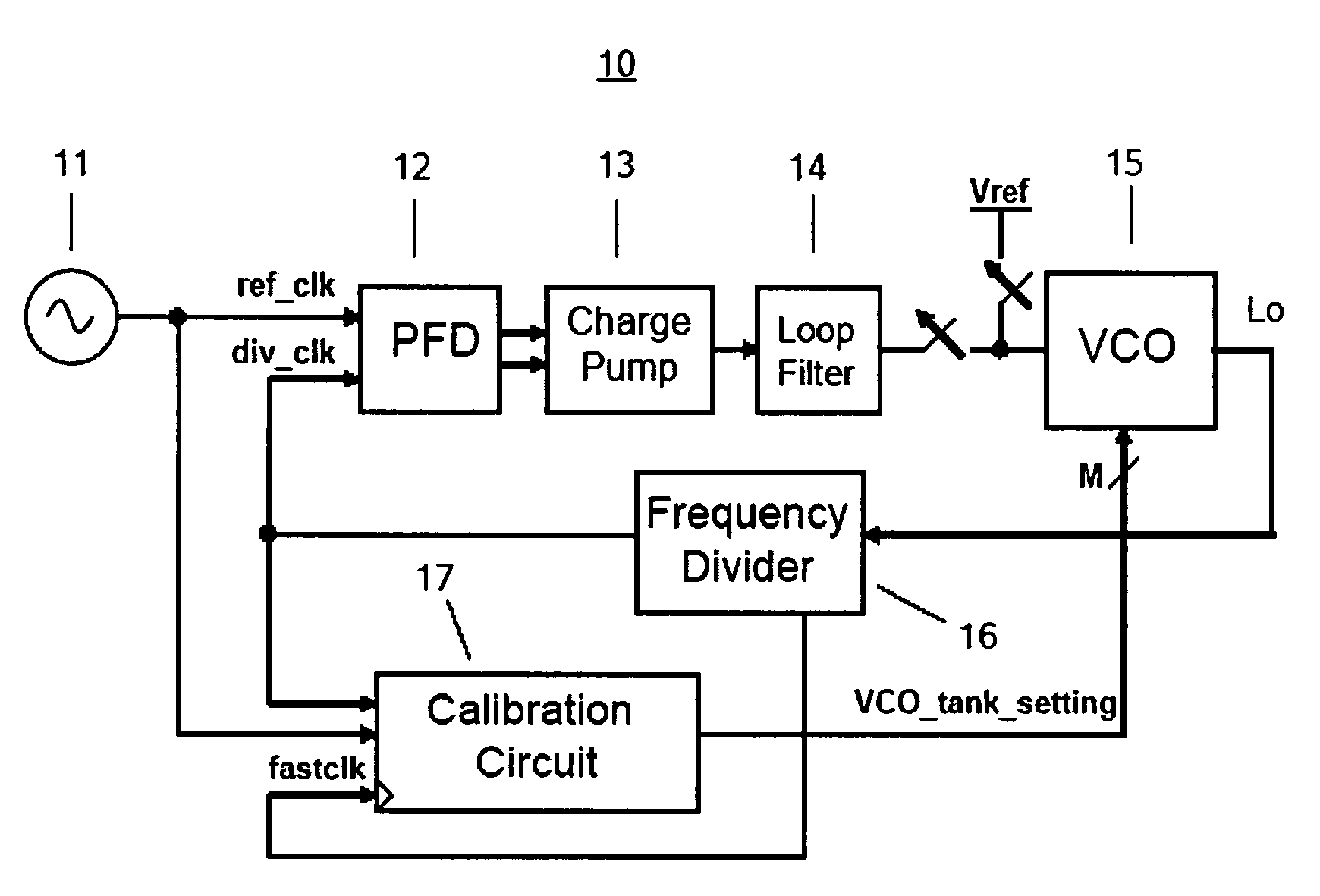
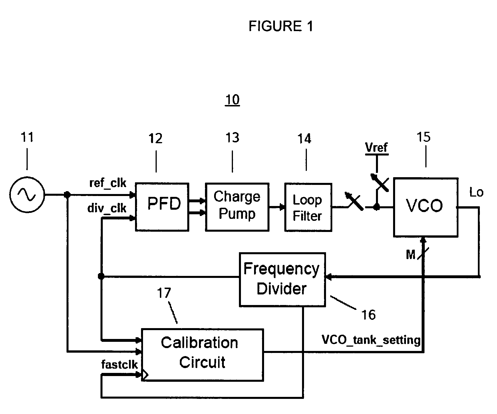
[0011]FIG. 1 illustrates a block diagram of an exemplary embodiment of a frequency synthesizer 10 that is consistent with the present invention. The frequency synthesizer 10 includes a phase-frequency detector (PFD) 12, a charge...


PUM


Abstract

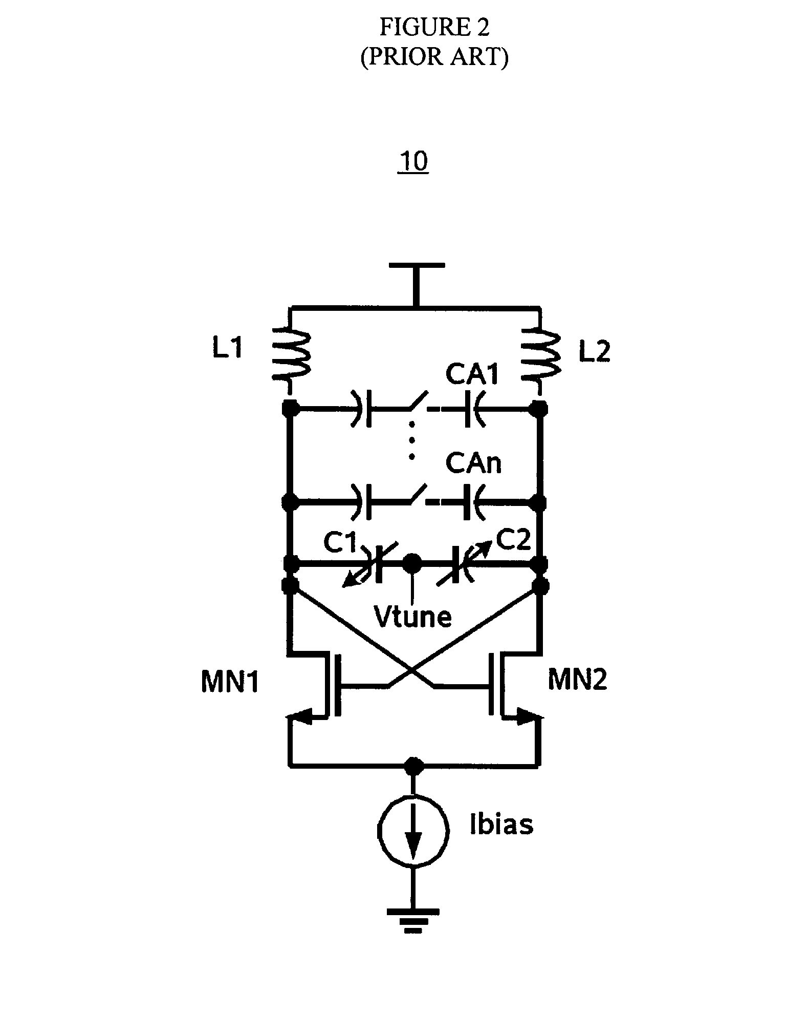
A calibration circuit (17) for calibrating a frequency synthesizer (10) having a voltage-controlled oscillator (VCO) (15) with a plurality of switched-capacitor arrays (CA1-CAn). The calibration circuit (17) counts a predetermined number of periods of the reference-clock signal (ref_clk) and divide-clock signal (div_clk) of the frequency synthesizer using a fast clock signal (fastclk). The fast-clock signal (fastclk) has a frequency greater than either the reference-clock signal (ref_clk) or the divide-clock signal (div_clk), enabling significantly faster calibration of the frequency synthesizer (10) than would be possible using the reference-clock signal (ref_clk). The calibration circuit (17) compares the count of the periods of the reference-clock signal (ref_clk) and the divide-clock signal (div_clk) and varies the tank signal of the VCO (VCO_tank_setting) until the count of the periods is substantially equal.

Description

FIELD OF THE INVENTION[0001]The invention relates generally to the frequency calibration of frequency synthesizers, and more specifically to the frequency calibration of frequency synthesizers having a voltage-controlled oscillator (VCO) with switched-capacitor arrays.BACKGROUND OF THE INVENTION[0002]Frequency synthesizers have a wide range of applications, including wide-band communications systems and information-processing systems. One of the elements of a frequency synthesizer is a voltage-controlled oscillator (VCO). A commonly used VCO is an inductive-capacitive (LC) VCO. In order to meet the requirements of modern wide-band frequency synthesizers, it has traditionally been necessary to utilize VCOs with large gains (Hz / V). However, chip integration has now increased to the point that VCOs with large gains often suffer from noise coupled through the voltage supply and substrate. In an effort to avoid this problem, prior art systems have begun to utilized VCOs with lower gains ...

Claims


Application Information

Patent Timeline
Patent Type & Authority Patents(United States)
IPC IPC(8): H03L7/00
CPCH03L7/099H03L7/113H03L7/18
Inventor WANG, STANLEYLEE, THOMAS H.
Owner MICROCHIP TECH INC
Learn More