Marking of pipe joints

a technology for welded pipes and joints, applied in the direction of pipe laying and repair, borehole/well accessories, drilling pipes, etc., can solve the problems of high cost and quick wear of the existing marking methods for pipe joints

Inactive Publication Date: 2009-01-06
PAPER CONVERTING MASCH CO INC +1
View PDF54 Cites 27 Cited by
  • Summary
  • Abstract
  • Description
  • Claims
  • Application Information

AI Technical Summary

Benefits of technology

[0009]Thus, the present invention provides an improved method of marking joint locations when used with screw thread connections or welding techniques, such as forge welding, fusion welding, diffusion welding, amorphous bonding, friction welding or other techniques in which a metallurgical bond is formed between abutted pipe ends. It preferably involves positioning a marker mid-wall in a tubular joint such that it is an integral part of the joint and cannot be dislodged.

Problems solved by technology

The existing methods for marking pipe joints are expensive, time consuming and may lead to a quick wear of the markings and replacement of worn markings may require retrieval of the entire pipe string from a well, which is very expensive.

Method used


Image

  • Marking of pipe joints
  • Marking of pipe joints
  • Marking of pipe joints

Examples


Embodiment Construction

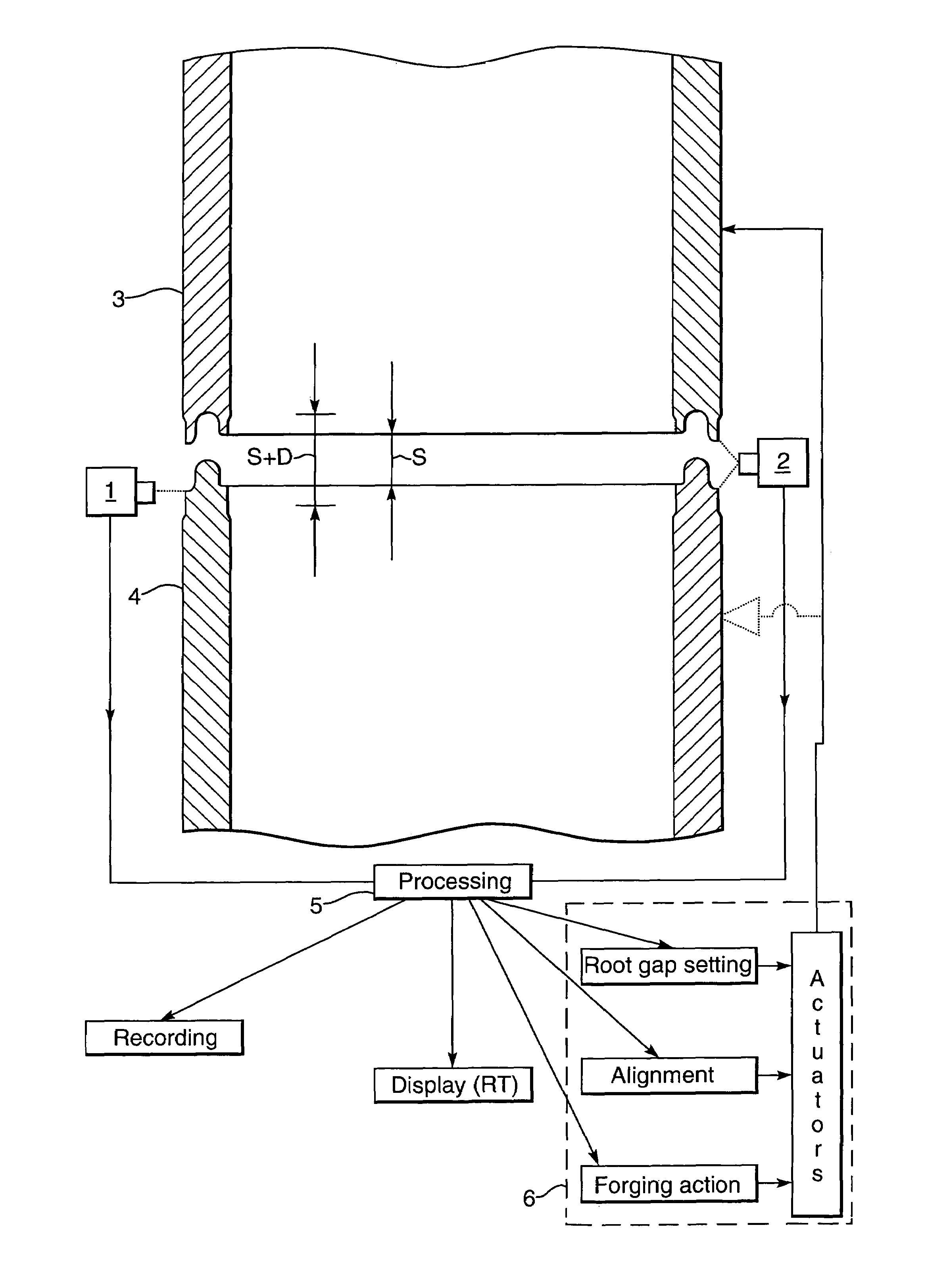
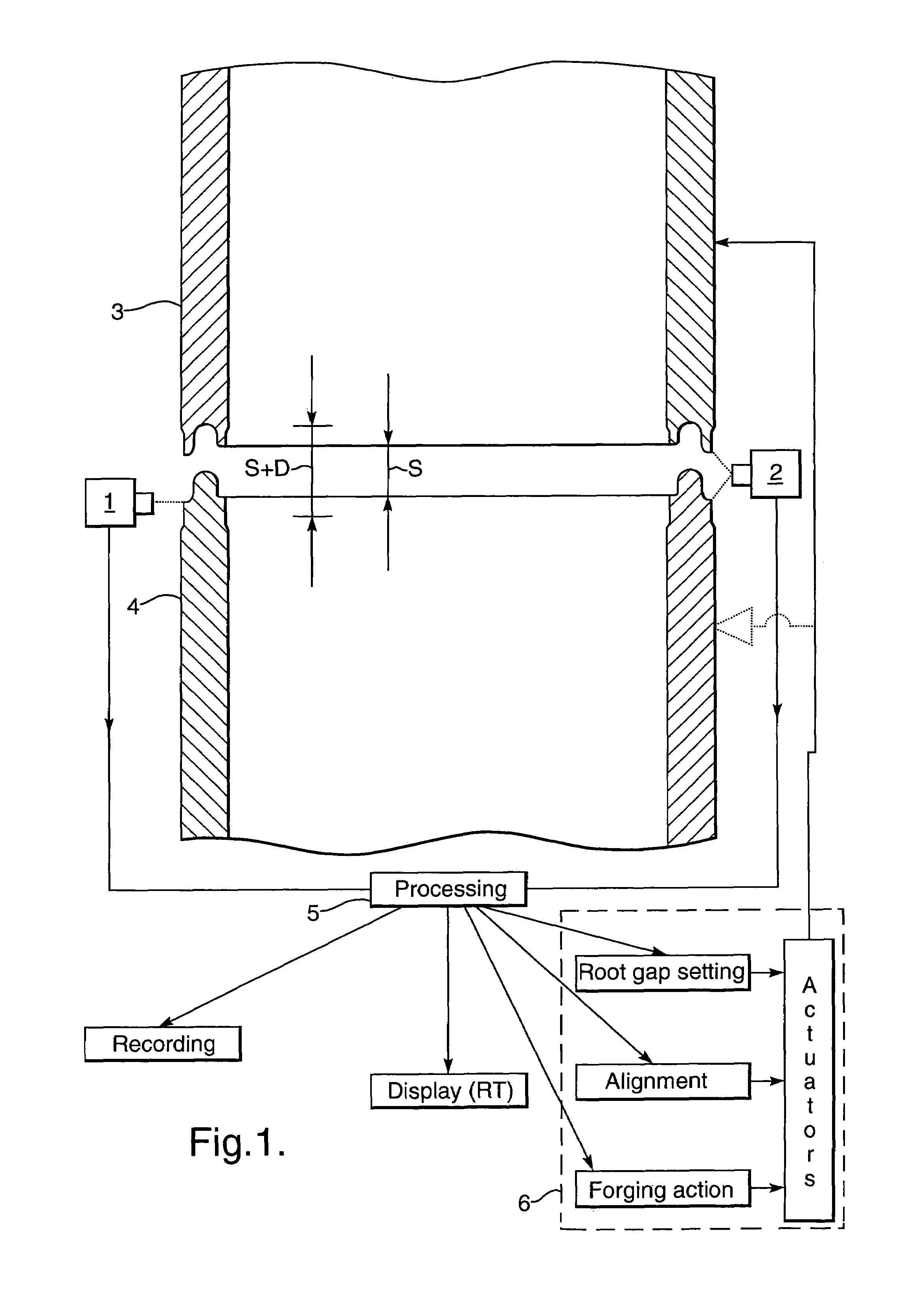
[0040]As shown in FIG. 1 the positions of the tubular ends 3 and 4 that are to be forge welded together are monitored by cameras 1 and 2 which are coupled to a camera signal processor 5 which automatically controls a gripping assembly 6, such that the spacing S between the heated tubular ends 3A and 4A is well defined during the heat up phase and the tubular ends are moved towards each other when a pyrometric control unit indicates that the tubular ends have reached a predetermined minimum and / or maximum temperature along at least a substantial part of the circumference thereof, whereupon the gripping assembly is activated to move the tubular ends 3A and 4A towards each other over a predetermined distance (S+D) which exceeds said spacing (S) with an additional distance (D) of less than a few millimeters, such that a forge weld is obtained of a substantially equal and high quality over the entire circumference of the forge welded ends and only minimal external and / or internal upsets ...


PUM

PropertyMeasurementUnit
lengthaaaaaaaaaa
temperatureaaaaaaaaaa
thicknessaaaaaaaaaa

Abstract

An improved method of permanently marking the location of a tubular joint, the method including creating a cavity into the end surface of one of the tubular ends that are to be joined by a forge weld or screw thread connection, inserting a marker into said cavity and subsequently joining the tubular ends.

Description

FIELD OF THE INVENTION[0001]The invention relates to a method for marking of welded pipe joints.BACKGROUND OF THE INVENTION[0002]When pipes are joined and used in for example a downhole, sub-sea or remote environment it is advantageous to log the position of individual pipes or to detect the position of individual pipes when the pipe and / or surrounding hole is re-entered. This is useful to e.g. allow accurate placement of side-tracks, packers and perforations.[0003]At the moment logging of this nature is done by measuring the distance a tool has travelled within or adjacent to the pipe, counting the number of connections or by positioning easily identifiable markers, such as magnetic or radioactive markers, in the hole alongside, and attached to, the pipe, which may be a production tubing and / or casing which marker may be found using specialized equipment. In addition special pup joints are often used for this purpose. The existing methods for marking pipe joints are expensive, time...

Claims


Application Information

Patent Timeline
Patent Type & Authority Patents(United States)
IPC IPC(8): G08B13/14E21B17/00E21B47/09F16L13/02F16L15/00G01V15/00
CPCE21B17/006E21B47/09F16L13/02F16L15/004G01V15/00F16L1/11Y10T29/49826Y10T29/49911Y10T29/4994F16L2201/60G06K19/07758
Inventor DEN BOER, JOHANNIS JOSEPHUSCOLE, ANTHONY THOMASDIMITRIADIS, KLISTHENISZIJSLING, DJURRE HANS
Owner PAPER CONVERTING MASCH CO INC
Why Eureka
Try Eureka