Drill bit

a drilling tool and bit technology, applied in the field of drilling tools, can solve the problems of high temperature during cutting, inability to achieve the desired effect of cooling lubricant, and complex design of cooling lubricant supply, and achieve the effects of easy chip removal, small fragmentation, and high temperature-dependent mechanical properties

Active Publication Date: 2009-01-13
KENNAMETAL INC
View PDF40 Cites 31 Cited by
  • Summary
  • Abstract
  • Description
  • Claims
  • Application Information

AI Technical Summary

Benefits of technology

[0010]The completely straight construction of the number of coolant channels corresponding to the number of cutting edges, but no less than two, favors efficient manufacturing of the drill bit. In addition, the continuously straight coolant channels also have flow-related advantages, especially when using minimal lubrication that operates using an air-oil mixture. Besides the low-resistance flow, not requiring the cooling lubricant to be rerouted within the drill bit is particularly relevant. Separation of the oil-air mixture, as may occur particularly with angular routing, is avoided. The tool can thus be used with small quantities of oil even at high machining speeds.
[0013]Compared to a coolant discharge on the tool's exterior, the discharge of the coolant at least generally in the tool's longitudinal direction has the advantage that cooling and / or lubrication is effective when applying the drill bit to the piece to be machined. In contrast, for outlet openings arranged on the tool's exterior through which the cooling lubricant is discharged radially outward with a movement component, the desired effectiveness of the cooling lubricant is not achieved before the drill bit along with the outlet opening penetrates into the workpiece.
[0014]In cutting operations, the cooling lubricant fed through the coolant channels preferentially does not strike the cutting edge, but rather strikes the chip formed by it or between the chip and the face. From a cross-sectional view of the tool, the twist angle between the outlet opening of the coolant channel and the cutting edge is at least −20° but no more than +45°, in particular at least −5° and no more than +15°. The angle of twist is thus defined as positive if the coolant channel's outlet opening precedes the tool's rotation. On the cutting edge not directly cooled by the cooling lubricant flowing out from the coolant channel's outlet openings, high temperatures may develop during cutting. This is particularly favorable for machining hard materials since thereby their typically highly temperature-dependent mechanical properties are intentionally utilized. The coolant jet striking the chip directly quenches it and thus tends to result in small fragmenting properties depending on the machined material. Thereby, one achieves the transfer of a large portion of the cutting heat to the chip and easy chip removal. The percentage of cutting heat transferred to the drill bit is kept comparatively low so that the drill bit expands only slightly during machining. This enables an especially high degree of manufacturing precision to be achieved during drilling.
[0015]The eccentric path of the coolant channels prevents weakening of the tool in the area of its axis. The mechanical stability of the entire tool is substantially influenced by the geometry of the flute. Preferentially, the flute's overall angle of twist, i.e., the angle between the cutting-side and shaft-side ends of the flute, is at least 90° and no more than 160°, especially at least 120° and no more than 160°. This results in a cross-sectional geometry of the drill bit on the shaft-side end of the flute that is especially well suited to absorb the forces incurred during cutting. The aforementioned angles refer to a dual-cutting edge drilling tool. For triple- and multiple-cutting edge drill bits, lesser overall angles of twist are advantageous.
[0016]The drill bit's flutes preferentially have a larger angle of twist in the area of the drill bit tip than in the area facing the shaft. The angle of twist increasing toward the tool tip, also referred to as side-rake angle, promotes simple chip removal, while the comparatively low angle of twist in the area facing away from the tool tip allows for a completely straight design of the coolant channels even for longer drill bit embodiments, for example for drilling depths of more than triple the drill bit diameter. Preferentially, the drill bit is fluted linearly in the area adjoining the shaft.

Problems solved by technology

The coolant supply is thus designed in a very complex manner.
In contrast, for outlet openings arranged on the tool's exterior through which the cooling lubricant is discharged radially outward with a movement component, the desired effectiveness of the cooling lubricant is not achieved before the drill bit along with the outlet opening penetrates into the workpiece.
On the cutting edge not directly cooled by the cooling lubricant flowing out from the coolant channel's outlet openings, high temperatures may develop during cutting.
The coolant jet striking the chip directly quenches it and thus tends to result in small fragmenting properties depending on the machined material.

Method used


Image

  • Drill bit
  • Drill bit
  • Drill bit

Examples


Embodiment Construction

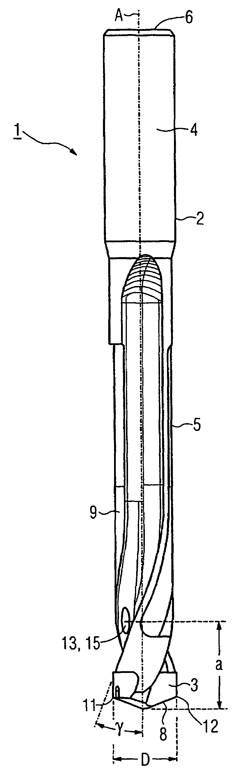
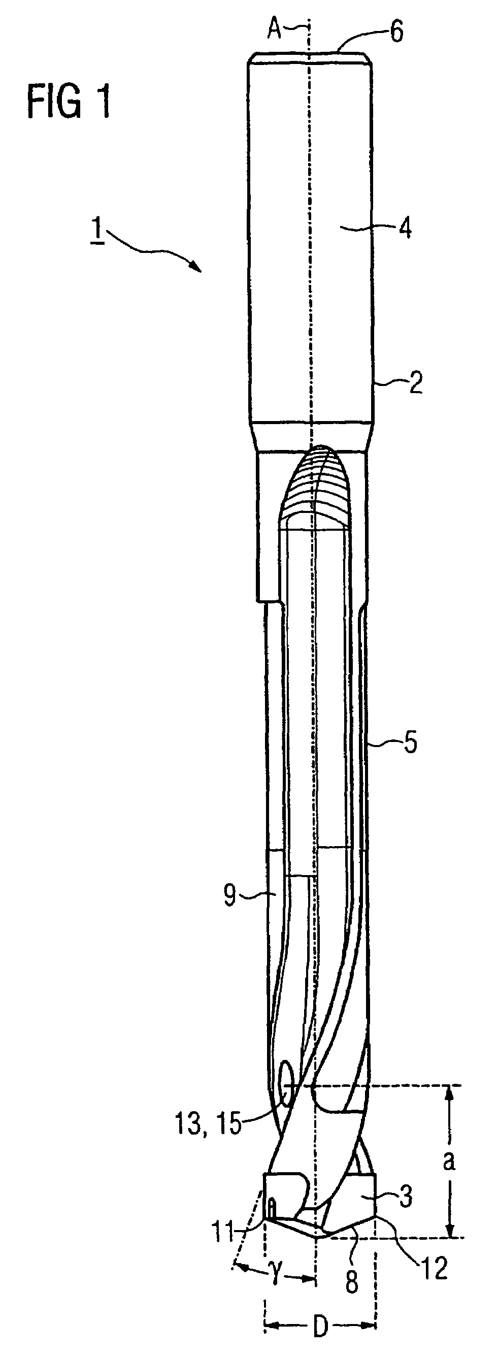
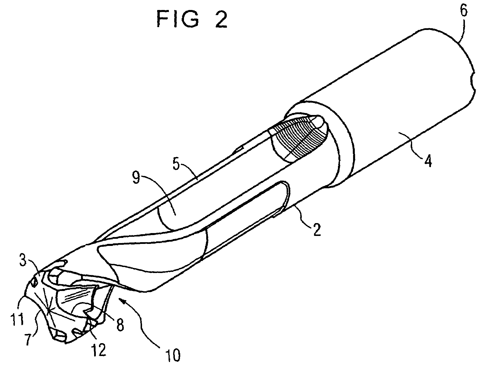
[0033]The same parts are labeled identically in all drawings.

[0034]FIGS. 1 and 2 depict an initial embodiment of drill bit 1, also referred to as tool, which is comprised of body 2 and tool tip 3. Body 2 is preferentially made of steel, while tool tip 3 is preferentially made of carbide metal. Differing from the embodiment depicted, drill bit 1 may also be made out of a single piece of carbide metal. Drill bit 1 may also have several exchangeable cutting elements, for example indexable inserts. All materials or parts thereof, including ceramics, conventionally used in cutting technology can be used as materials for drill bit 1. For cutting elements or coatings, polycrystalline diamonds (PCD) or cubic boronitride (CBN) are suitable. In at least one embodiment, the entire drill bit 1 is made integrally as a single piece without any interchangeable parts or portions.

[0035]Drill bit 1 comprises shaft 4 to which is attached a cutting part 5, which in turn comprises tool tip 3. Shaft 4, w...


PUM

PropertyMeasurementUnit
twist angleaaaaaaaaaa

Abstract

A drill bit having a shank portion and a cutting portion, which cutting portion generally has at least one cutting edge and a chip flute that has a helical portion. The drill bit has at least one straight coolant channel that has a coolant exit orifice disposed at least partially in the flute and oriented toward the cutting edges to supply coolant thereto to cool the cutting edges and chips produced during a cutting operation.

Description

CONTINUING APPLICATION DATA[0001]This application is a Continuation-In-Part application of International Patent Application No. PCT / EP2004 / 005974, filed on Jun. 3, 2004, which claims priority from Federal Republic of Germany Patent Application No. 103 33 340.1, filed on Jul. 23, 2003. International Patent Application No. PCT / EP2004 / 005974 was pending as of the filing date of this application. The United States was an elected state in International Patent Application No. PCT / EP2004 / 005974.BACKGROUND[0002]1. Technical Field[0003]The present application relates to a drilling tool, especially for metallic materials, with generally at least two cutting edges and each with an at least partially spiraled flute extending from the cutting edges toward the tool shaft. This type of a drill bit is known from EP 0 750 960 B1, for example.[0004]2. Background Information[0005]Machining tools, especially drill bits, are often operated using cooling lubricants that are supplied to the tool's cutting...

Claims


Application Information

Patent Timeline
Patent Type & Authority Patents(United States)
IPC IPC(8): B23B51/06
CPCB23B51/06B23B2251/046Y10T408/9097Y10T408/455B23B2251/50B23B51/00
Inventor BORSCHERT, BERNHARDKRENZER, ULRICHBUTTNER, RAINER
Owner KENNAMETAL INC
Why Eureka
Try Eureka