Orthotic apparatus and method for using same

Inactive Publication Date: 2009-01-20
ERMI
View PDF45 Cites 25 Cited by
  • Summary
  • Abstract
  • Description
  • Claims
  • Application Information

AI Technical Summary

Benefits of technology

[0022]It is a further object of the present invention to provide an orthotic device which has increased reliability.
[0023]It is a further object of the present invention to provide an orthotic device which is easy to apply and remove.
[0024]It is a further object of the present invention to provide an orthotic device which allows for instant release of pressure. It is a further object of the present invention to provide an orthotic device which provides a high load application
[0025]It is a further object of t

Problems solved by technology

Obviously, this is a disadvantageous condition and should be corrected if possible.
This is difficult to do particularly if the joint to be treated is the arm needed to strap the brace.
Furthermore, the pressure on each limb segment by each cuff is very painful as the joint is bent or straightened.
Lastly, the ratchet system does not allow for instant release of the pressure used to force an increase in the range of motion.

Method used


Image

  • Orthotic apparatus and method for using same
  • Orthotic apparatus and method for using same
  • Orthotic apparatus and method for using same

Examples


first embodiment

FIGS. 1-4

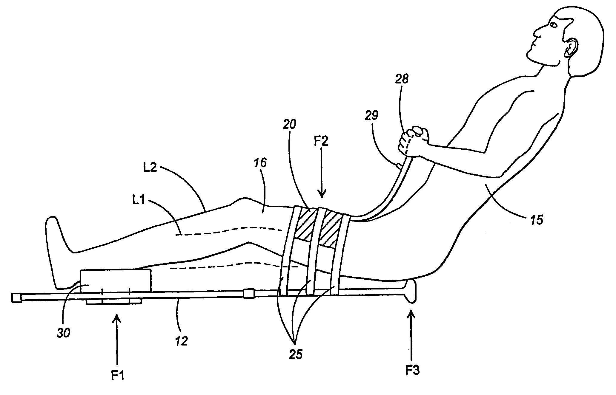
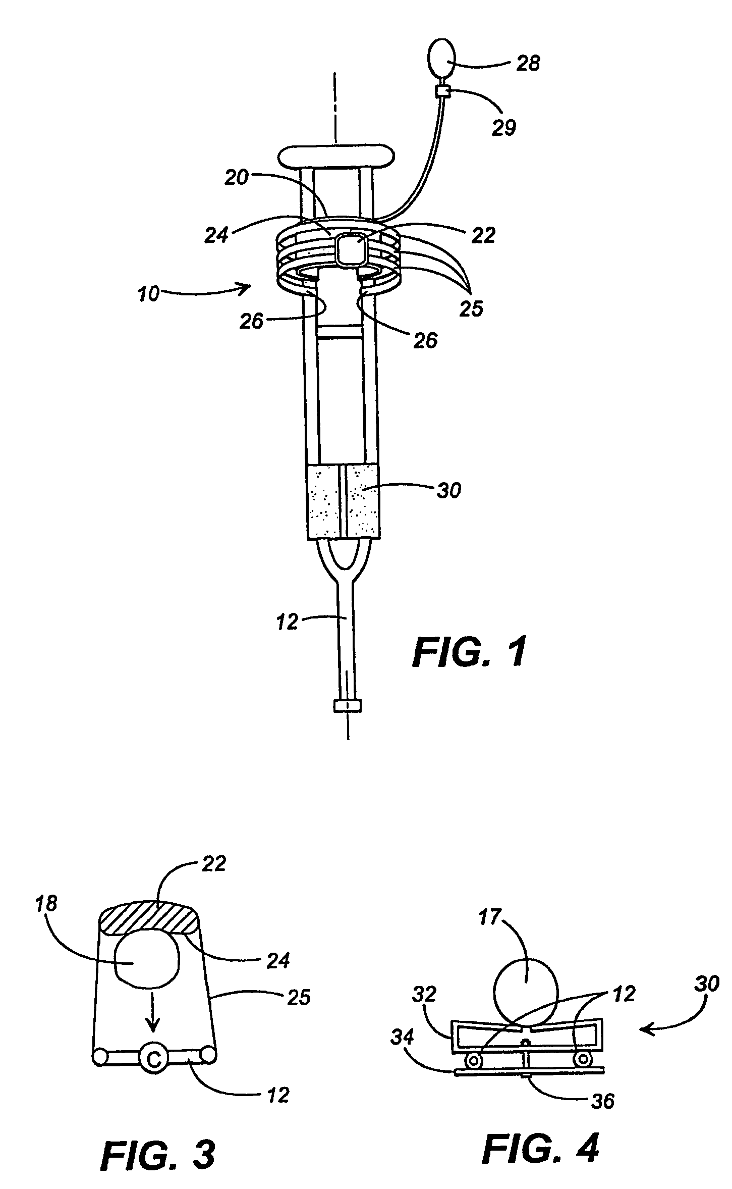
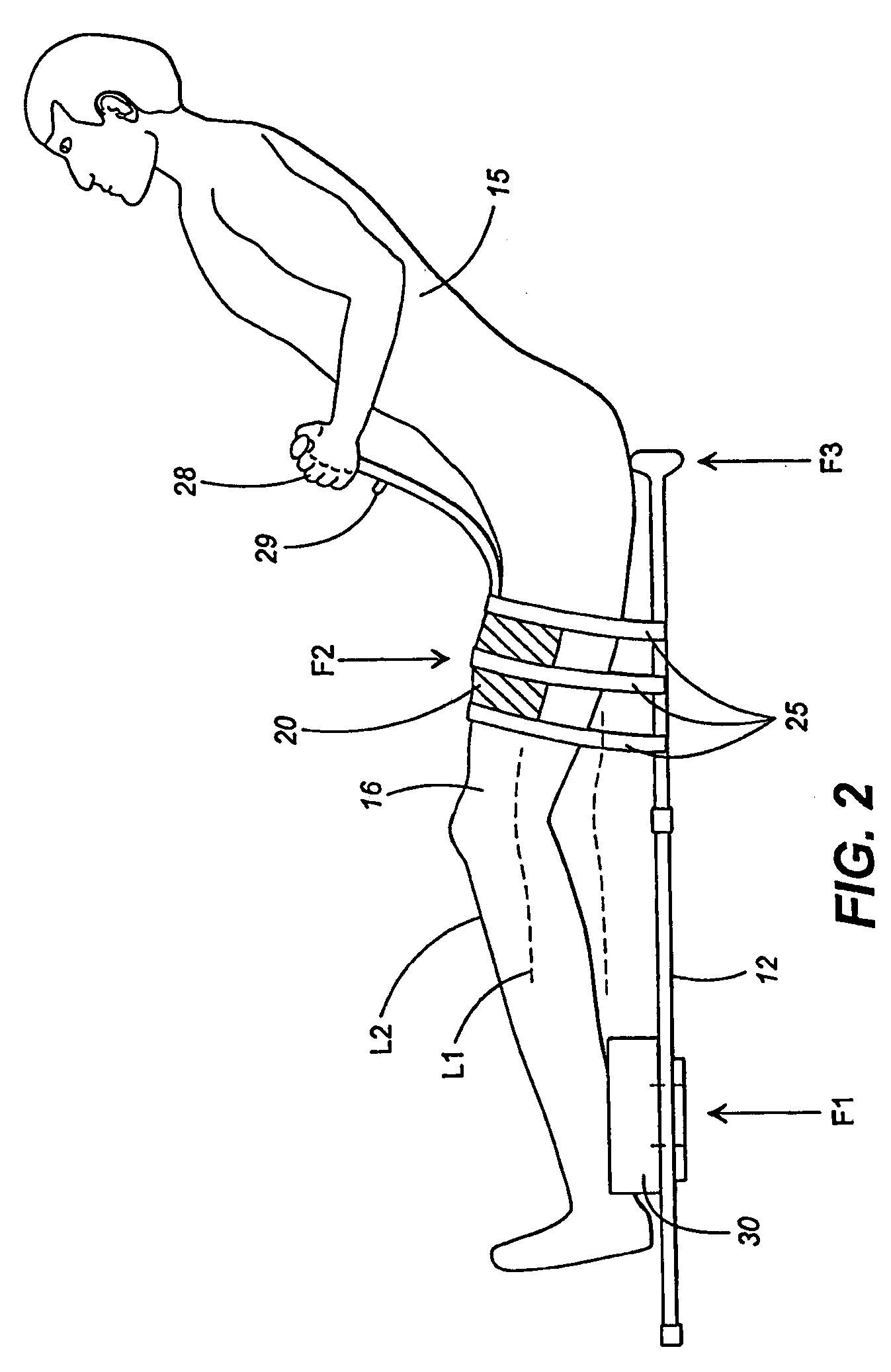
[0050]FIG. 1 is a front view of a knee extension assembly 10 and an ankle support member 30 used in conjunction with a conventional crutch 12. FIG. 2 is a is a side view of the elements 10, 12, 30 being used by a wearer 15. FIG. 3 is a top cross-sectional view taken transverse to the longitudinal axis of the crutch and the wearer's leg of FIG. 2, with the cross-section taken through the inflatable air bladder. FIG. 4 is another transverse cross-section taken from the FIG. 1 configuration, but this time the cross-section is taken just above the ankle support member 30.

[0051]The crutch as shown in FIG. 1 is a conventional type of crutch, which is a distinctive aspect of the present invention in that conventional crutches are readily available within the market. The present invention particularly adds the use of a knee extension assembly 10 and an ankle support member 30.

[0052]The knee extension assembly 10 includes an inflatable member 20, a plurality of straps 25, and a conv...

second embodiment

FIG. 5

[0060]FIG. 5 illustrates the use of a rigid plastic or other suitable material, to provide an elongate structural member 210 which may be attached to the underside of the arm, with its lower end extending beyond the elbow, terminating in a “free end”. Approximate this “free end” are attached three (as shown) straps 225 which connect an inflatable member 224 (an air bladder in a fabric pouch) to the free end of the elongate member. This member 224 is configured to be positioned adjacent to the forearm of a wearer, such that inflation of the air bag therein tends to provide pressure causing movement such as shown as M. This is conventionally called “extension” and is desired in certain types of orthotics.

[0061]It should be understood that this FIG. 5 configuration includes the “three point” force combination as described above. However, this FIG. 5 configuration is similar to the FIG. 6 and 7 configuration, and the “three point” force configuration will be described in more deta...

third embodiment

FIGS. 6 and 7

[0062]FIGS. 6 and 7 show a third embodiment of the present invention, being an apparatus 300 configured to be attached to the arm of a wearer 315. It should be understood that FIG. 6 is a more simplified version.

[0063]The apparatus 300 includes a substantially rigid structural frame 301 including a forearm bearing portion 302 and an upper arm bearing portion 304, connected by one or more connecting members 306. Also included are straps 325 and an inflatable member 324 which can include an inflatable bladder contained by a fabric pouch. As are other configurations discussed herein, the straps are sewn to the fabric pouch by conventional means. As elsewhere in this discussion VELCRO-type attachments at 327 may be provided for detachability and adjustability of the straps.

[0064]Flanges 305 (see FIG. 7) may be optionally used if desired to extend upwardly on either side of the main body to contain the forearm as desired.

[0065]FIG. 7 shows the embodiment in slightly more det...


PUM


Abstract

An inflatable bladder position a distance from a joint is attached to an external structural support which crosses the joint but does not support it. By inflating the bladder one limb segment is forced towards the external support thereby increasing the ranges of motion of that joint. Further, the inflatable bladder has an instant release valve which, when pressed, will instantly release the pressure within the bladder. The limb is positioned intermediate the bladder and the external structural support for optimal biomechanical efficiency.

Description

CROSS REFERENCE TO RELATED APPLICATIONS[0001]This application is a continuation of U.S. application Ser. No. 09 / 779,329 filed Feb. 8, 2001, which was a. U.S. continuation of International Application No. PCT / US99 / 18074 filed Aug. 10, 1999, which claimed the benefit of Provisional Application No. 60 / 096,105 filed Aug. 10, 1998; Provisional Application No. 60 / 096,104 filed Aug. 10, 1998, and Provisional Application No. 60 / 095,952 filed Aug. 10, 1998.TECHNICAL FIELD[0002]This invention relates generally to orthotic devices and more particularly to orthotic devices designed to promote an increase in range of motion in a joint by the use of selectively inflatable and deflatable bladders.BACKGROUND OF THE INVENTION[0003]When a joint is injured either by trauma or by surgery scar tissue can form which prevents full range of motion of that joint. Obviously, this is a disadvantageous condition and should be corrected if possible. Often, such correction involves an attempt by the injured or t...

Claims


Application Information

Patent Timeline
IPC IPC(8): A61F5/00A61F5/01A61H1/02A61H23/04
CPCA61F5/012A61H1/0237A61H1/0274A61H2201/0134A61H2201/0103A61H1/024A61H1/0266A61H1/0277A61H1/0285A61H1/0288A61H3/02A61H2201/0119A61H2201/1238A61H2201/1253A61H2201/1638A61H2201/1642A61H2201/1635A61H2201/164
Inventor BRANCH, THOMAS P.
Owner ERMI
Why Eureka
Try Eureka