Vehicle cooling package

a cooling package and vehicle technology, applied in the field of automobile cooling packages, can solve the problems of high under hood temperature, significant backpressure on the fan and recirculation of heated air, and achieve the effect of reducing under hood temperature, quieter and more efficien

Inactive Publication Date: 2009-01-27
DEERE & CO
View PDF28 Cites 29 Cited by
  • Summary
  • Abstract
  • Description
  • Claims
  • Application Information

AI Technical Summary

Benefits of technology

[0004]Another object of the invention is the provision of an improved cooling package which significantly reduces under hood temperatures as well as the heat load on the operator's station.
[0005]A further object of the invention is to provide an improved cooling package which is effective to expel a large quantity of the heated fan exhaust away from the vehicle and does not stir up excess dust and debris near the vehicle.

Problems solved by technology

This results in high heat loads on the cab, high under hood temperatures, significant backpressure on the fan and recirculation of heated air to the cooling system.

Method used


Image

  • Vehicle cooling package
  • Vehicle cooling package
  • Vehicle cooling package

Examples


Embodiment Construction

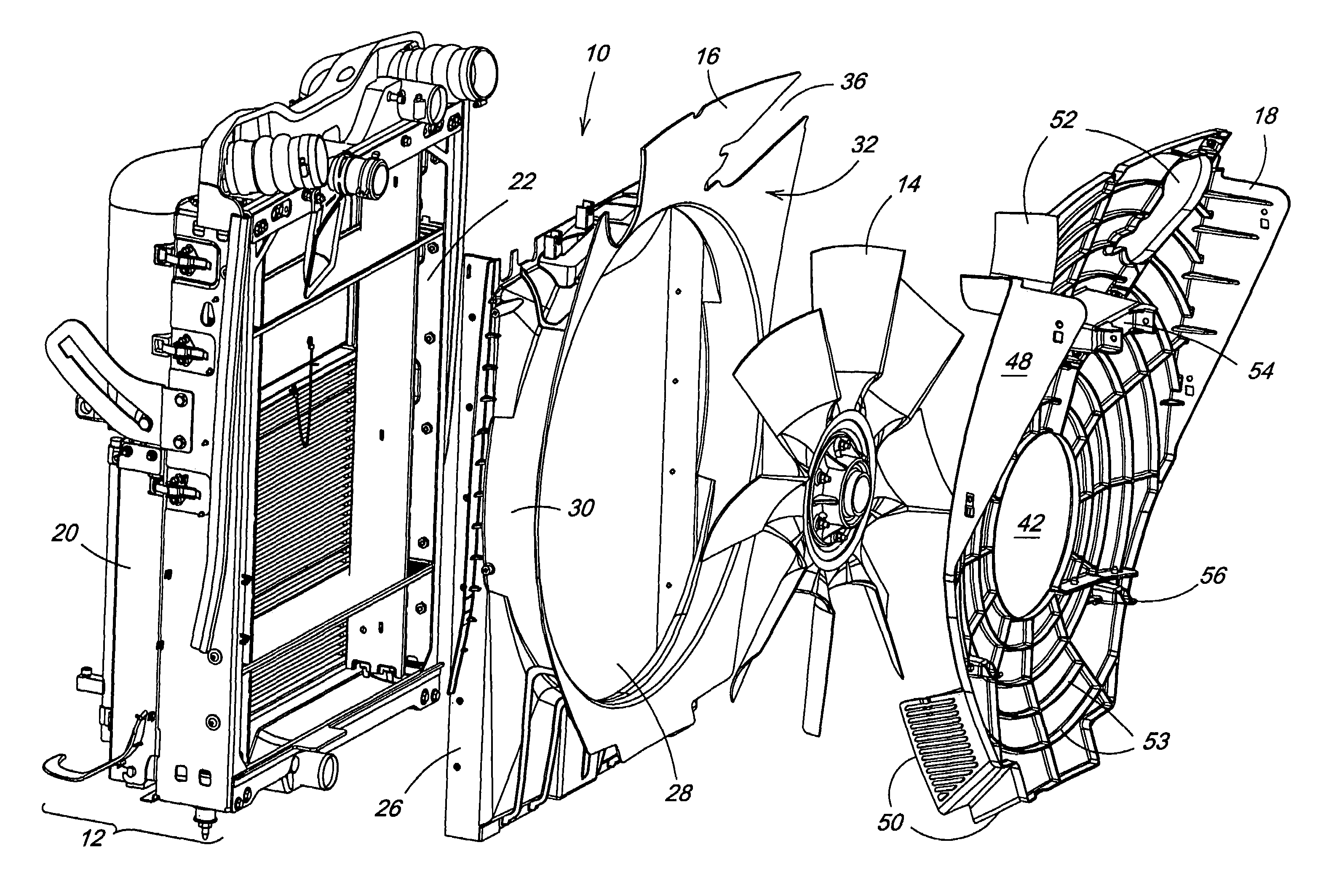
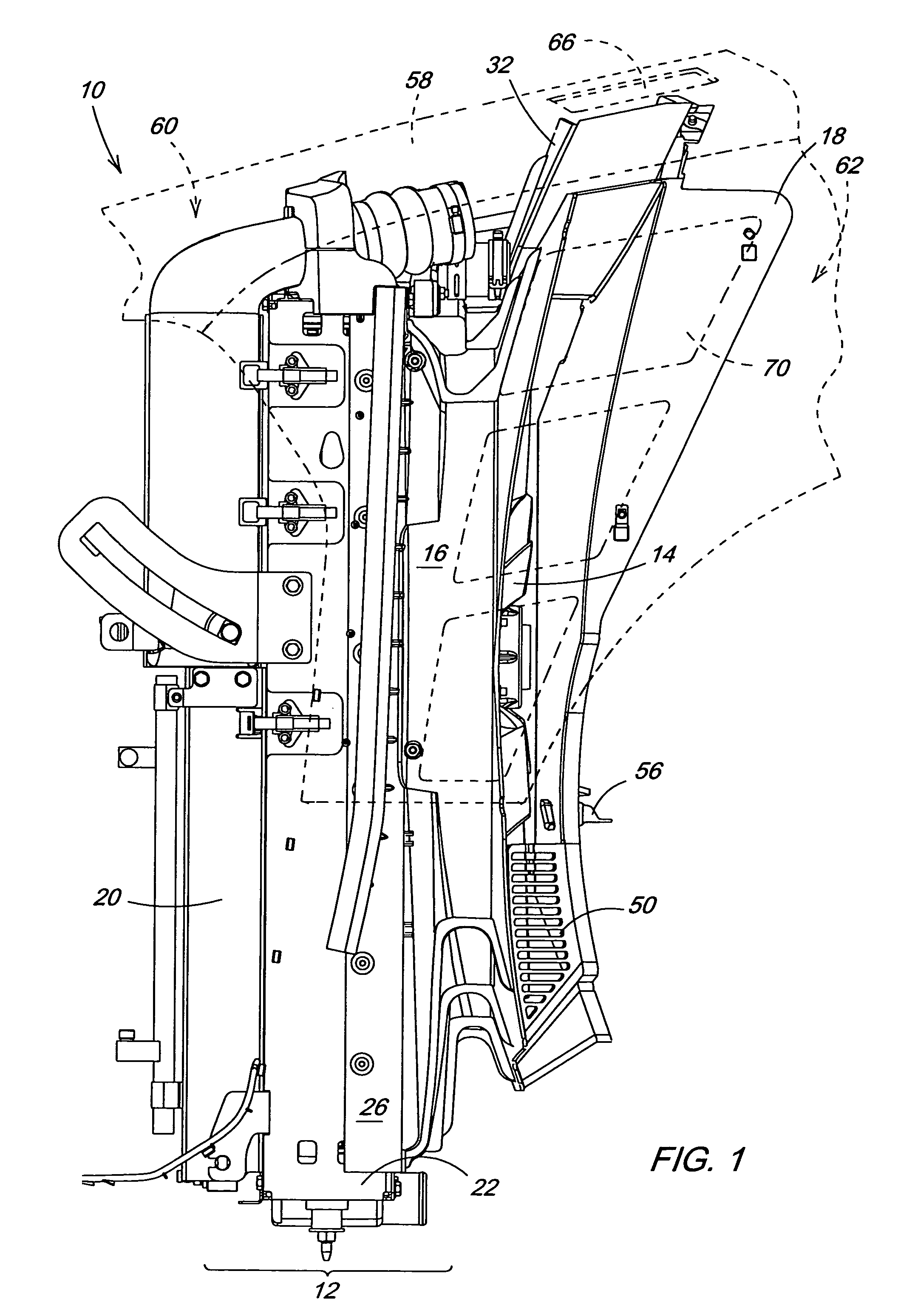
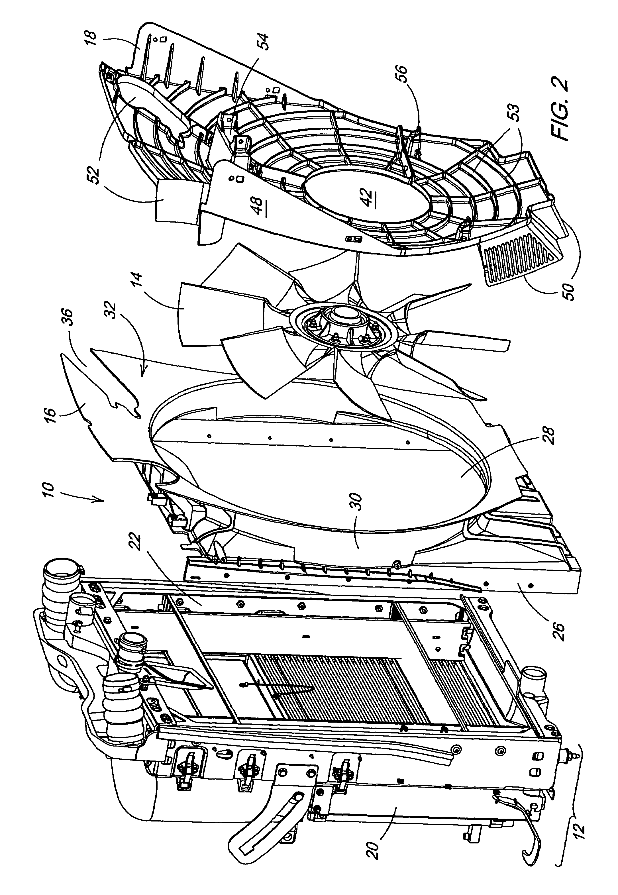
[0026]With reference now to the drawings, and particularly to FIGS. 1 and 2, it can be seen that a vehicle cooling package according to the invention is designated generally by the numeral 10. As shown the cooling package 10 is comprised generally of a heat exchanger assembly 12, a fan 14, a fan shroud 16 and a diverter plate 18. The heat exchanger assembly 12 typically comprises one or more heat exchangers 20 in the form of charge air coolers, oil coolers, radiators, fuel coolers, air conditioning condensers or the like, mounted to a frame 22. The fan shroud 16 is preferably mounted to the frame 22 and thus provides a generally enclosed air passage between the heat exchanger(s) 20 and the fan 14, which is partially disposed within the shroud 16. The diverter plate 18 is mounted to the fan shroud 16, or other vehicle attachment points, but is sufficiently spaced from the shroud 16 such that the fan 14 is interposed generally between the shroud 16 and the diverter plate 18.

[0027]Refe...


PUM


Abstract

A vehicle cooling package has a fan shroud mounted to a heat exchanger assembly. A diverter plate is mounted adjacent to the shroud and spaced therefrom with a fan interposed therebetween. A diverting surface of the shroud and the diverter plate are angled from the axis of the fan when the shroud and plate are assembled to the vehicle. A vehicle hood has upper and side surfaces each having air discharge apertures corresponding with the space between the diverting surface and the diverter plate when the hood is closed. The diverting surface and the diverter plate both extend fully to the hood assembly when the hood is closed. The angles of the diverting surface and the diverter plate closely match a natural discharge angle of the fan, so that air is discharged from the fan at a high velocity from under the hood through the air discharge apertures.

Description

FIELD OF THE INVENTION[0001]The present invention relates generally to automotive vehicles such as work vehicles like agricultural tractors. More particularly, the present invention relates to such vehicles having internal combustion engines. Specifically, the present invention relates to cooling packages for such vehicles.BACKGROUND OF THE INVENTION[0002]Agricultural tractors in production today typically direct a significant portion of the cooling system fan exhaust under the hood enclosure and over the engine. A large amount of fan exhaust, both under the hood and outside the hood imparts heat to the operator station (cab). This happens due to the direction of the air being discharged from the cooling system and the fact that such air naturally tunnels through the hood enclosure toward the cab. This results in high heat loads on the cab, high under hood temperatures, significant backpressure on the fan and recirculation of heated air to the cooling system. Recirculation of heated...

Claims


Application Information

Patent Timeline
Patent Type & Authority Patents(United States)
IPC IPC(8): B60K11/04F01P1/00F01P1/06F01P5/06F01P11/10F04D29/58
CPCF01P5/06F01P11/10F01P2001/005B60K11/04B60K11/06B60Y2200/221
Inventor MADSON, RICKY DEANAPPLETON, ANDY BLAINELAFFERTY, CLINTON LANEBURK, RONNIE FRANKLINBOWMAN, DENNIS AARONTOCK, THOMAS FREDERICKBRUSS, PAUL THOMASWARREN, CHARLES NICHOLASFARLOW, SCOTT KEITHOLIVER, MATTHEW ROBERT
Owner DEERE & CO
Why Eureka
Try Eureka