Expandable mask stent coating method

Inactive Publication Date: 2009-01-27
BOSTON SCI SCIMED INC
View PDF15 Cites 78 Cited by
  • Summary
  • Abstract
  • Description
  • Claims
  • Application Information

AI Technical Summary

Benefits of technology

[0017]The foregoing method is amenable to a number of variations. For example, the coating may be allowed to dry before the balloon is deflated, thereby minimizing the potential for wet coating to flow onto previously masked surfaces when the balloon is removed. Alternatively, the balloon may be immediately removed and the stent placed on a mandrel while the coating dries, thereby permitting the balloon to be more quickly made available for reuse. The balloon itself also may be made to resist adhesion of the coating on its outer surfaces, e.g., coated with or made from a material to which the coating does not adhere, in order to minimize or prevent “bridging” of the coating material across the openings in the stent lattice. Alternatively, the balloon may be encased in an expanding sleeve with similar coating repellant properties, such that when the balloon ex

Problems solved by technology

When the amount of coating is insufficient or is depleted through stripping of poorly adherent coating during manufacture or deployment within the patient's body, the implant's effectiveness may be compromised, and additional risks may be inured into the procedure.
For example, when the coating of the implant includes a therapeutic, if some of the coat

Method used


Image

  • Expandable mask stent coating method
  • Expandable mask stent coating method
  • Expandable mask stent coating method

Examples


Embodiment Construction

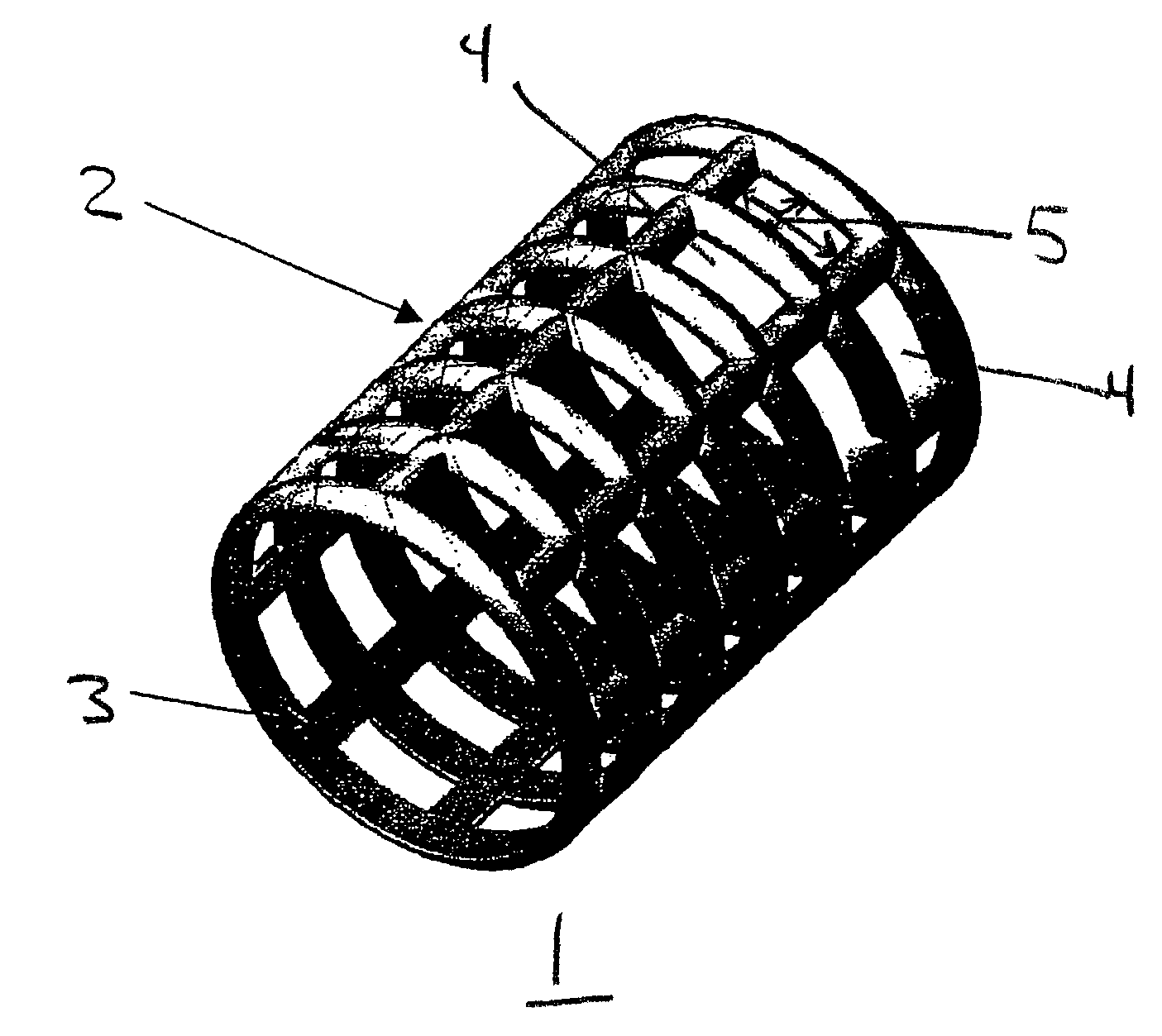
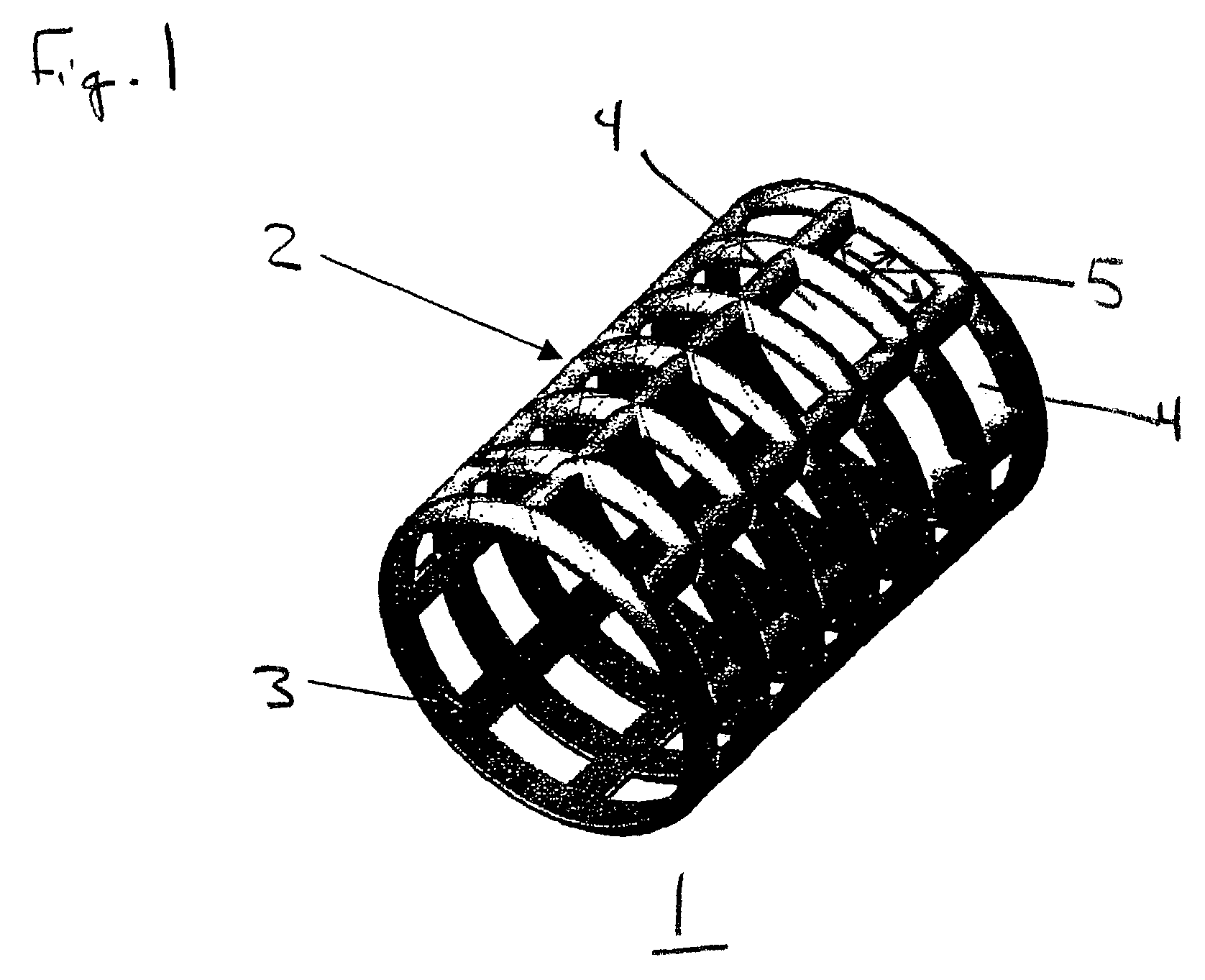
[0022]FIG. 1 illustrates a stent 1 which is to receive a coating of a therapeutic material. As shown in the figure, stent 1 is generally cylindrical in shape, and is in the form of a lattice of a material such as stainless steel, Tantalum, Platinum or Nitinol alloys. Stent 1 has an outer surface 2 that will contact the inner wall of a lumen such as a blood vessel (not shown), and thus is to be coated with a therapeutic coating material to be delivered to the lumen wall. The stent also has an inner surface 3 that will be in contact with the fluid carried by the lumen. Inner surface 3 is to be maintained coating-free. The lattice configuration of stent 1 provides interstitial openings 4. Facing these openings, the stent structure has lateral surfaces 5 between the outer surfaces and the inner surfaces.

[0023]The present method is not limited to the stent lattice configuration shown in FIG. 1, as any of a variety of well-known stent configurations may be used. The cross-sectional shape ...


PUM

PropertyMeasurementUnit
Lengthaaaaaaaaaa
Areaaaaaaaaaaa

Abstract

A system and method for selective masking of stents using an expandable masking balloon to prevent deposition of therapeutic or protective coatings on portions of the stent during a coating application process. An expandable balloon is located within the inner region of a stent, the balloon is inflated until its outer surface contacts and the inner surface of the stent lattice in the areas in which the stent coating is not to be applied, thereby masking the stent inner surface from deposition of stent coating material during a stent coating process, and the coating is applied to the remaining exposed surfaces of the stent, for example by spraying or dipping the stent. The balloon is then deflated and removed from the coated stent. The balloon may be coated with, or formed from, a material impregnated with polytetrafluoroethylene to discourage adherence of the coating material to the balloon's outer surface in order to minimize coating waste and bridging of stent lattice openings by coating films.

Description

FIELD OF THE INVENTION[0001]The present invention is directed to an improved method for applying therapeutic and protective coatings to stents. More specifically, the present invention pertains to a method for selective application of a coating to the outer surfaces of a stent while preventing the stent's interior surfaces receiving coating material.BACKGROUND[0002]Medical implants are used for innumerable medical purposes, including the reinforcement of recently re-enlarged lumens, the replacement of ruptured vessels, and the treatment of disease such as vascular disease by local pharmacotherapy, i.e., delivering therapeutic drug doses to target tissues while minimizing systemic side effects. Such localized delivery of therapeutic agents has been proposed or achieved using medical implants which both support a lumen within a patient's body and place appropriate coatings containing absorbable therapeutic agents at the implant location. Examples of such medical devices include cathet...

Claims


Application Information

Patent Timeline
IPC IPC(8): A61L33/00B05D3/00A61F2/00A61L31/10B05B15/04
CPCA61L31/10B05B15/0456A61F2250/0067B05B12/24
Inventor BOULAIS, DENNIS R.
Owner BOSTON SCI SCIMED INC
Why Eureka
Try Eureka