Fan speed control system

a control system and fan technology, applied in the direction of dynamo-electric converter control, electrical apparatus casing/cabinet/drawer, instruments, etc., can solve the problems of hardly an optimal solution, power consumption considerations primarily applied to portable equipment using battery power, etc., to prolong the life of the fan used for cooling, reduce noise, and reduce power consumption

Inactive Publication Date: 2009-01-27
SEMICON COMPONENTS IND LLC
View PDF64 Cites 68 Cited by
  • Summary
  • Abstract
  • Description
  • Claims
  • Application Information

AI Technical Summary

Benefits of technology

[0012]Having the fans operate at maximum speed at all times is hardly an optimum solution, however. It would be desirable for the fans to run at the minimum speed appropriate for the particular temperature to minimize acoustic noise and power consumption, as well as to prolong the life of the fans used for cooling. Of course, the power consumption considerations apply primarily to portable equipme

Problems solved by technology

Having the fans operate at maximum speed at all times is hardly an optimum solution, however.
Of cou

Method used


Image

  • Fan speed control system
  • Fan speed control system
  • Fan speed control system

Examples


Embodiment Construction

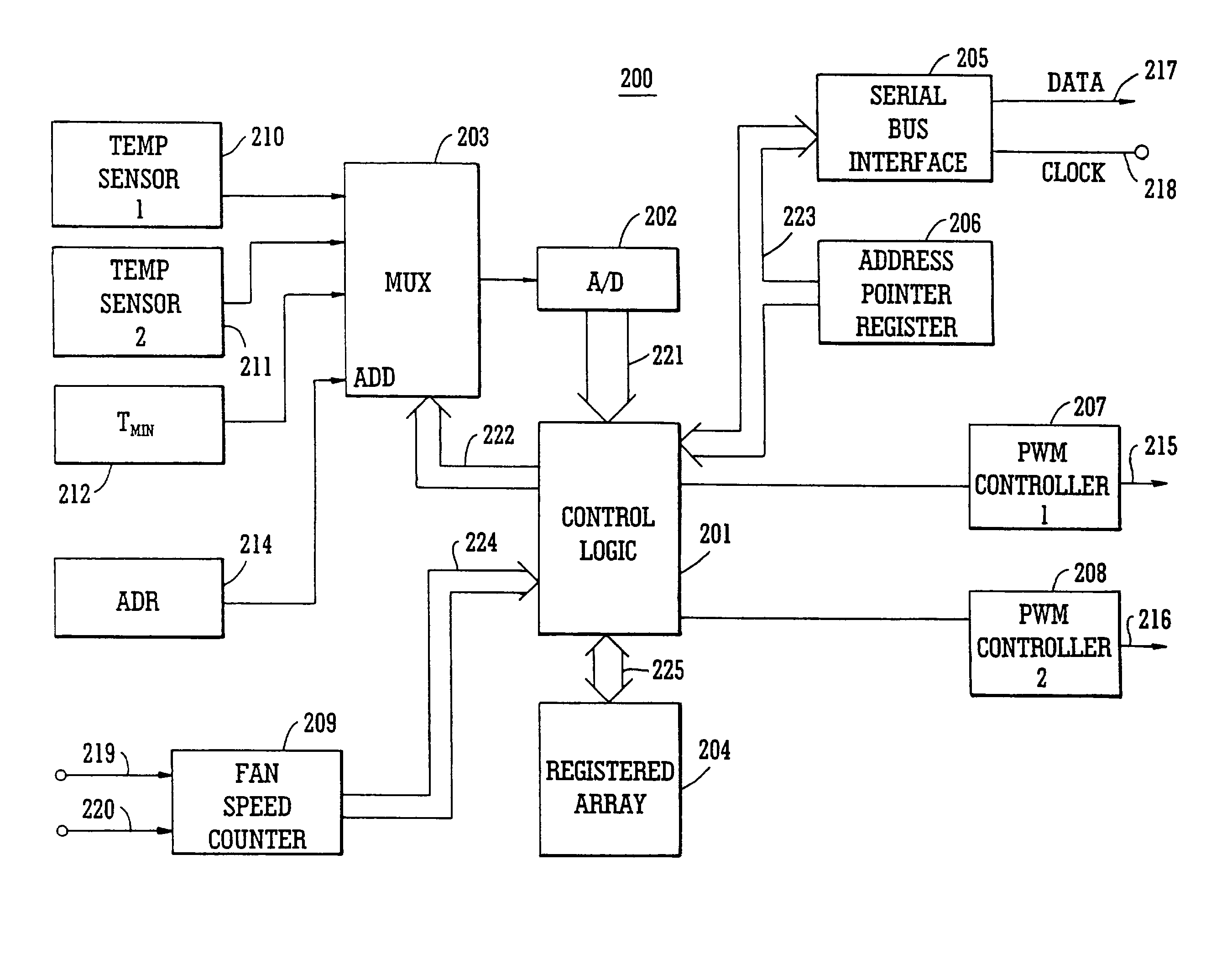
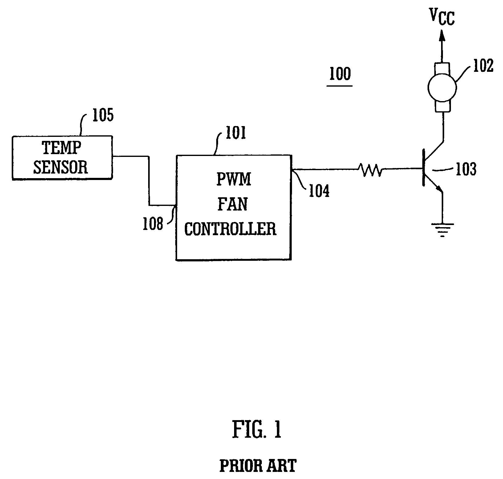
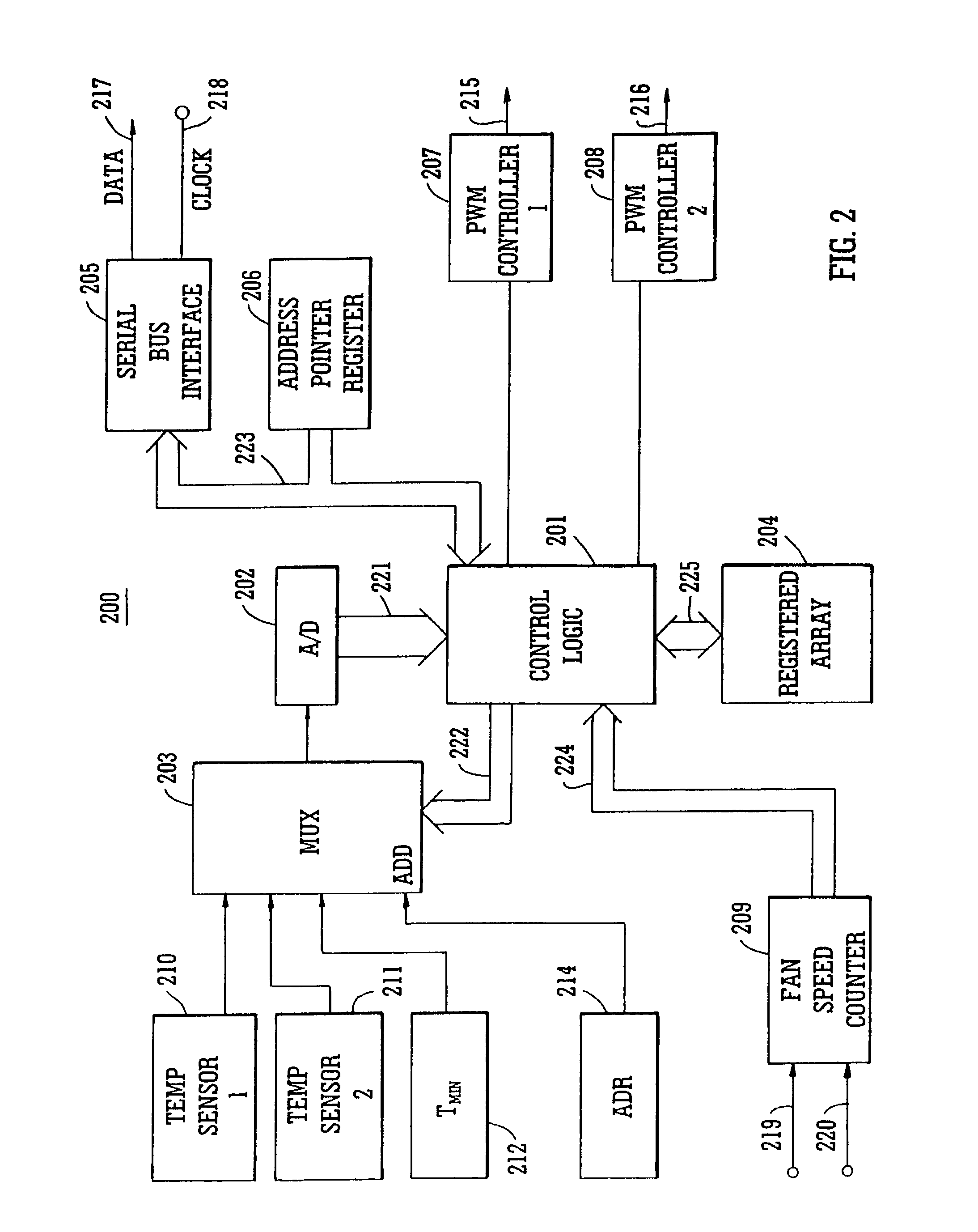
[0045]In accordance with the present invention, a fan speed control system is described that provides distinct advantages when compared to those of the prior art. FIG. 1 illustrates a fan control system well known in the prior art, generally depicted by the numeral 100. A pulse-width modulation (PWM) controller integrated circuit (IC) 101 has as its primary control input a signal from a temperature sensor 105, that is received over input signal line 108. The temperature sensor 105 may be an appropriately biased thermistor, for example, selected to have a known resistance at a predetermined reference temperature (25° C., for example). Of course, even though the present system utilizes temperature information for fan speed control purposes, it would also be possible to use other operating parameters, such as, for example, air flow at selected locations within an equipment enclosure. Air flow velocity information could readily be represented by a varying voltage.

[0046]It is well-known ...


PUM


Abstract

A fan speed control system (200) for an electronic equipment enclosure comprises means for determining temperature (201, 202, 203, 210, 211) at a plurality of locations within the enclosure, means for determining operating parameters (201, 202, 203, 212) for the fan control system, means for setting operating speed (201) of at least one cooling fan, and means for exchanging information signals (205, 217, 218) relating to fan speed control system operation with an external controller. A method is also provided for controlling fan speed for an electronic equipment enclosure comprising the steps of determining temperature at a plurality of locations within the enclosure, determining operating parameters for the fan control system, setting operating speed of at least one cooling fan, and exchanging information signals relating to fan speed control system operation with an external controller.

Description

[0001]This application is a 35 U.S.C. §120 continuing application of application Ser. No. 10 / 168,434, filed on Oct. 15, 2002 now abandoned, entitled FAN SPEED CONTROL SYSTEM; which is a U.S. national stage entry of prior International application No. PCT / IE00 / 00149, filed on 18 Dec. 2000, entitled FAN SPEED CONTROL SYSTEM, which is a continuation of prior application Ser. No. 09 / 470,800, filed on Dec. 23, 1999, entitled FAN SPEED CONTROL SYSTEM and now issued as U.S. Pat. No. 6,188,189 on Feb. 13, 2001.FIELD OF THE INVENTION[0002]This invention relates generally to fan speed control and in particular to a fan speed control system for electronic equipment enclosures, and is more particularly directed toward a fan speed control system that communicates with an external processor resource while retaining some autonomy, and utilizes pulse width modulation to maintain a predetermined relationship between fan speed and equipment temperature.BACKGROUND OF THE INVENTION[0003]Electronic equi...

Claims


Application Information

Patent Timeline
IPC IPC(8): G06F1/20H05K5/00H05K7/20F04D27/02G05B13/02G05D23/00
CPCF04D27/004H05K7/20209F24F11/0079Y02B30/746F24F11/77Y02B30/70
Inventor BLAKE, JOHN
Owner SEMICON COMPONENTS IND LLC
Why Eureka
Try Eureka