Method of mounting a metal sheet ring assembled and welded in a carrier hoop to conform the annular cooling tube of a piston of internal combustion engine

a technology of internal combustion engine and carrier hoop, which is applied in the direction of engine cooling apparatus, domestic applications, applications, etc., can solve the problems of undesirable cracks, complex methods, and no base for welding, and achieves the effect of reducing the number of welded parts

Inactive Publication Date: 2009-02-03
APPO ROBERTO OSCAR
View PDF7 Cites 10 Cited by
  • Summary
  • Abstract
  • Description
  • Claims
  • Application Information

AI Technical Summary

Benefits of technology

[0057]The present invention relates to a mounting that is used for the binding and assembly of the metal sheet ring on the carrier hoop, the assembly making sure that the ring is kept duly positioned and fixed on the carrier hoop before the welding is carried out, not requiring the use of stress due to differences of thermal expansion, and providing a highly convenient and secure backing to the welding bead.
[0088]No previous welding is required for the ring manufacturing, thus eliminating from the beginning the possibility of welding faults.

Problems solved by technology

The disadvantage, in this case, is particularly the precision required for the mutual coupling of the two pieces that provides the correct adjustment of the cooling tube such that, when used, no undesirable cracks occur due to relative movements of these elements bound by the welding bead.
This welding, which has neither a base nor a backing, is very difficult to be carried out.
It is only possible by means of sophisticated methods that are of a very high operative cost.
Furthermore, the paths being assembled should be mechanized with very low tolerances such that, in any case, the interferences that should take place are always maintained.
That is to say, thermal expansion is used to get the desired and stable positioning of the pieces to be bound, which in turn, besides being of high cost, if such binding of pieces is not carried out properly, takes the risk that stresses taking place during the use of the piston may cause undesirable cracks.
Apart from the above mentioned, it is contemplated that this construction only makes possible the constitution of cooling tubes limited to a “U” cross section pattern of parallel faces, which is highly restrictive, as there exist many pistons designs of other section formats according to various requirements.
The main problem for all these embodiments consists of achieving a very good assembly and positioning of the “U” section metal sheet on the inside surface of the carrier hoop, this being rather difficult and generally of a high cost, above all for the previously mentioned tasks of assembly, positioning and also welding that have to be carried out.
It is especially mentioned that in this mounting, no backing fitting for the welding bead that determines the union of both components, is required, the process being difficult to be carried out and insecure as regards the air tightness required.
The disadvantage or inconvenient of this mounting is that the adjustment of the folding is limited by the body itself of the carrier hoop that prevents the metal sheet from being firmly adjusted before the welding.
It is not possible to assure that the metal sheet will be properly assembled at the desired position, exerting adequate pressure against the body of the carrier hoop, before the welding process.
If this condition is not met before and during the welding process, such process may be affected.
Also noted is the limitation that the inside surface(s) of the carrier hoop should not generate a truncated cone seat for the ends of the fins of the “U” profile that forms the metal sheet ring.
If the seat steps are not present, the welding of the fins is carried out without support, which is not certainly secure.
Especially noted is that, whenever an assembly is carried out as the one achieved with the mounting disclosed by U.S. Pat. No. 6,105,540, the welding bead that fixes the assembly will not have a stable backing, because the supports of the free ends of the fins of the “U” profile of the metal sheet ring have a reduced surface.
This represents a high cost of installation.
This patent states that, with the conventional technique, no metal sheet rings can be effectively produced.
In case another profile design or cross section is required, another construction die specially designed for each case is introduced, thus considerably increasing the manufacturing costs.

Method used


Image

  • Method of mounting a metal sheet ring assembled and welded in a carrier hoop to conform the annular cooling tube of a piston of internal combustion engine
  • Method of mounting a metal sheet ring assembled and welded in a carrier hoop to conform the annular cooling tube of a piston of internal combustion engine
  • Method of mounting a metal sheet ring assembled and welded in a carrier hoop to conform the annular cooling tube of a piston of internal combustion engine

Examples


Embodiment Construction

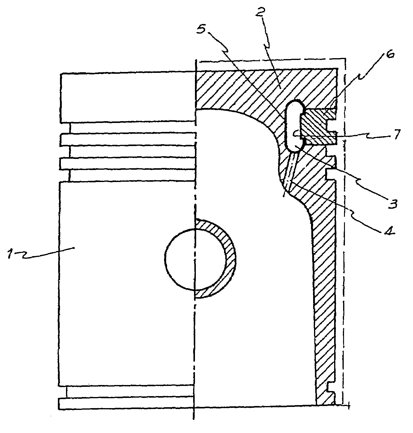
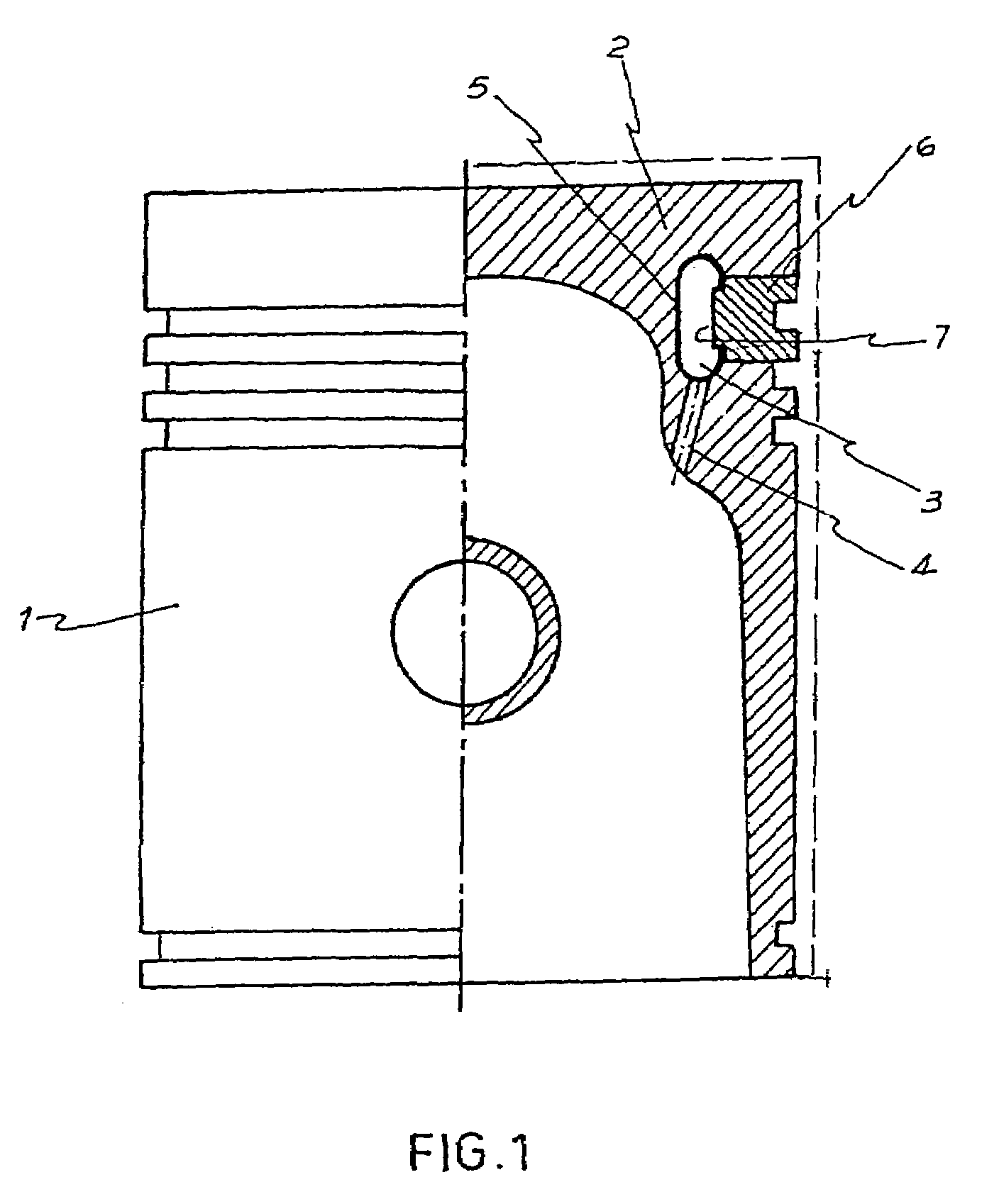
[0129]As can be appreciated from FIG. 1, the mounting referred to in connection with the present invention is intended to be applied to a piston 1 used by an internal combustion engine.

[0130]As is well known, the piston, together with the rings (not illustrated), should effectively seal the combustion chamber to avoid the entrance of hot gas and lubricant oil in any work condition. On the other side, it is already known that portion 2, usually called the piston head, is more exposed to the thermal and mechanical requirements. Therefore, there currently exist various pistons that include a cooling gallery or tube 3 arranged in the body of the head 2.

[0131]The purpose of the cooling gallery or tube 3 is to counteract the heating in the piston head 2 when the temperature is excessive. Thus, a cooling liquid, such as the engine oil, circulates through the cooling tube 3 that, by passing through passages 4 (one of which is shown), communicates with the inside of the piston. That is to sa...


PUM

PropertyMeasurementUnit
angleaaaaaaaaaa
thicknessaaaaaaaaaa
widthaaaaaaaaaa

Abstract

A metal sheet ring (5) has a web (15) extending between two fins (10) and (11) projecting towards a carrier hoop (6), wherein free ends of the fins rest on and couple to respective annular seats (8) and (9) defined in an internal face of the carrier hoop, the free ends being sealed by respective annular welding beads (14) to form an internal annular cooling tube (3) having an inside surface constituted by the metal sheet ring and the inside surface (7) of the carrier hoop. For the support and coupling of the ring (5) on the carrier hoop, a preform of the ring, formed outside of the carrier hoop, has a preform fin (10′) open at an angle slightly greater than the angle of the other preform fin (11) and with a free end of smaller diameter than the inside surface diameter (7) of the carrier hoop (6), while the other preform fin (11) has a larger diameter than the diameter of the inside surface (7) of the carrier hoop (6) in a way that a final stamping action, which is the only action performed with the preform in the carrier hoop, gives the final configuration to the fin (10) of the metal sheet ring (5).

Description

[0001]The present invention relates to a method of mounting a metal sheet ring assembled and welded in a carrier hoop to form the annular cooling tube of a piston of an internal combustion engine, and a method of manufacturing a fin metal sheet ring assembled with a carrier hoop.[0002]More particularly, this invention contemplates a mounting of a metal sheet ring assembled and welded to a carrier hoop capable of being engaged with the pistons of internal combustion engines and forming a internal cooling tube, usually called a cooling gallery.[0003]This invention refers to a manufacturing method especially created to form a finned metal sheet ring of such a type that, once assembled and welded to a carrier hoop, is coupled to the body of a piston of an internal combustion engine to form an internal cooling tube, also called a cooling gallery.[0004]As it is well known, the pistons used in internal combustion engines, particularly in diesel engines, are subject to extreme thermal condi...

Claims


Application Information

Patent Timeline
Patent Type & Authority Patents(United States)
IPC IPC(8): B21K1/18F01P3/10B21DB21D53/18B23PB23P15/06B23P15/10F02FF02F3/00F02F3/22F16J1/09F16J9/00F16J9/22
CPCB23P15/06B23P15/10F02F3/22F16J1/09F16J9/22F02F2003/0007Y10T29/49274Y10T29/49252Y10T29/49256Y10T29/49279Y10T29/49258B21D53/18
Inventor APPO, ROBERTO OSCAR
Owner APPO ROBERTO OSCAR
Why Eureka
Try Eureka